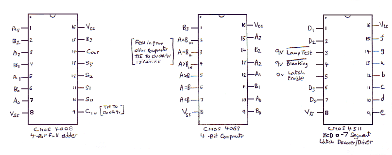
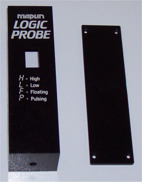
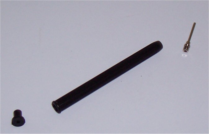
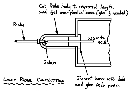
| 7-segment Logic Probe Case | Logic Probe Tip | Tip Assembly Instructions | ||
 |
 |
 |
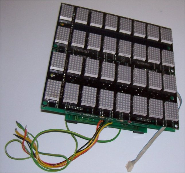 Dotmatrix Scroller with 4-Line 8-Character 5x7 RED-GREEN-YELLOW LED's with embedded controller and external RS422 interface. £49 each from
Display Electronics. 100's in stock, bought up from Greenweld. Many being used in commercial applications right now. Requires power supply also (can power 3 panels).
 supplies PC to Display Panel interfaces (professionally made blank PCB + pre-programmed PIC) at £25 each including UK delivery; and EDF (Enhanced Display fireware) EPROM's at £10 for pack of 3 including UK delivery. He designed and constructed them himself and will provide basic technical advice on how to set them up and run them. I built and ran one panel with his help from my PC using his older control system about 8 years ago, using a power supply I bought from Greenweld. The power supplies are no longer available but Robert Coward's Data Sheet:
Display Release 29-09-06.zip [1.42 MBytes] provides alternate types you can use, plus information about the whole system.
All computers have Microprocessors (...their brains!) and all Microprocessors have an ALU (arithmetic and logic unit) where simple mathematical operations are performed. Just about any conceivable program you run. from a wordprocessor to computer game needs to add up. This is one function of the ALU. Computers don't add up in decimal as I'm sure most of you are aware but use the simplest number system there is: Binary. Just 1's and 0's.
Decimal numbers can however be represented in Binary by using BCD (Binary code decimal). 4 Binary Bits give a range 0-15. So if you only use 0-9 four bits can represent one Decimal digit. The ALU uses Binary however as this is more efficient, taking numbers (generally 8 or 16 bits) and adding them. An 8 bit number can be 0-255 so if for example you added 150 to 200 the result would be 350 i.e. higher than 255. So the result is stored in one Byte (8 bits) and a carry bit is set in the microprocessors status register (H.Q., mission control?) if the number exceeds 255. This allows a computer program to take account of this on a slightly higher level.
The 'Calculator' in the Science Museum worked in a similar way. Two numbers were set as input in the BCD range 0-9. Toggle wheels were used to select them. For those of you who don't know, toggle wheels are finger operated rotary switches with settings 0-9 that output the result via 5 wires. 4 for the BCD result and 1 to provide logic 1 to these lines where appropriate. My circuit then uses an 8 SIL (single in line) resistor network to provide pull up resistors for both toggle wheels i.e. the output of these resistors from their common is active unless signals from the toggle wheel override it. A further 4 contacts also allow the output to be in negative logic. Useful in some applications where you want to save logic gates by a cleaver fiddle. But I didn't need them in this case.
My toggle wheels have gold plated contacts. Gold, Silver and Copper are the best conductors because electrons circle the atom in groups, and the final group in these and only these materials has an outer group of 1 electron making it easiest to detach. Physicists call them shells. You will note their weight goes up in the order Copper, Silver, and Gold. And the price. Gold is the best conductor but also the most expensive due to rarity. The toggle wheels for this reason cost me about £5 each when I bought them some years ago. Higher weight atoms of similar characteristic could also be theoretically good conductors. Unfortunately they are so heavy they can not hold together and particles shoot off i.e. they are radioactive.
Heavy metals are made - when stars go supernova under the extreme conditions that then occur. They then drift in space until captured by a young star forming e.g. the sun and part of the material forms into inner planets. The material must also have been in another former star to turn light elements into medium weight elements that then go to make up part of the second star. Therefore the particles that make up gold have been through two star lives and then been captured by a third. Hence their extreme rarity with the ' process taking billions of years and covering light years of space.
Getting back to the subject at hand. The BCD out from the toggle wheels is sent to a 4511 CMOS BCD-to- 7 -segment converter IC. CMOS chips work at 3-15V so can be driven from a 9V PP3 battery. This is all that is needed to power the circuit. The output of the converter is then feed through an 8 DIL (dual in line) I resistor network. Basically 8 resistors in one package: easier to solder. The output of the network goes to a 7-segment digital LED display. So whatever the BCD number is the corresponding number appears on the display.
The resistors are needed to ensure each segment of the display is of equal brightness. For example is you have 'I'. this uses only 2 segments, `9' however uses 6 segments. But all the segments are sinked through the same line so `1' would be 3 times as bright as `9' as more current would pass through fewer segments. This would give a very bad final effect.
The output from the toggle wheels is also feed to a CMOS 4008 4-Bit Binary Adder, giving a 5-bit result between 0 and 18. The table below details all possible combinations in binary and decimal:
00000 =	0 (0 + 0)
00001 =	1
00010 =	2
00011 =	3
00100 =	4
00101 =	5
00110 =	6
00111 =	7
01000 =	8
01001 =	9
01010 =	10 (> 0100X)
01011 =	11
01100 =	12
01101 =	13
01110 =	14
01111 =	15
10000 =	16
10001 =	17
10010 =	18 (9 + 9)
As can be seen any result between 0 and 9 can be dealt with easily. The problem arises when the result is greater than 9 i.e. between 10 and 18. The first thing to do is too find out which case the circuit is currently dealing with. To do this a CMOS 4063 4-bit comparator can be used. `Although the result is 5-bits the 5th bit can be disregarded in the case when looking for a greater than 9 option, as the table shows above.
The comparator gives an output (A>B) when the result is 10 or above. This is feed to two further sections of the circuit. One: through a biasing resistor and transistor to driver the 2-segment `1' display (second result digit). It displays `1' for 10 or above :and is blank for 9 or below. The display I used requires a 9V supply so activating it means linking it to OV via the transistor. Two spare resistors from the resistor networks are used to maintain constant brightness as with the other LED displays.
Two: A>B goes to a second 4-Bit Binary Adder. It is configured so an active line feeds in 6 to the B input and an inactive line 0. Input A derives from the 4 LSB's of the 5-bit result. As the 4-bit result is in hexadecimal (base 16) it has to be converted to BCD (base 10). This is done by adding 6 to the result if it is 10 or other. The `1' has been dealt with above. The 4-bit result is sent to a 7-segment display as above for the inputs.
The PCB I used was only single sided as they are easier to design and etch. But this does have the drawback of having to use wire on top to jump over tracks. I had to use 23 top wires. I believe the PCB layout below can be photocopied onto a transparency and used to etch your own circuit, it is the bottom view.
