This is a very simple digital circuit that simulates one set of traffic lights. The timing is longer for the Red and Green only stages than the Amber and Red/Amber stages but the timing probably isn't absolutely right. Anyway many modern traffic lights are controlled by computers and monitored using cameras from a traffic control centre and are switched in a way that reduces road congestion, meaning timing may vary. This circuit could be built using a PIC micro-controller but many members may not have the necessary skills or equipment to do this. Of course I would welcome other members with PIC experience writing a follow up article about how to make this circuit using a PIC. The circuit only requires three chips showing that SSI (Small Scale Integration) chips are still useful in some applications and is a good introduction to digital electronics. You don't even have to know how to solder to build this circuit or have a power supply.
The chips used are actually CMOS which stands for Complementary MOS. MOS is a form of transistor used internally in the IC. It comes in two types PNP and NPN. Most IC's like TTL use two or more transistors and a resistor to create NAND gates. NAND can be used to create any other type of logic gate. You could try working this out as an exercise for each type of logic gate, just draw up some logic tables to help you. The trouble with this is the resistor continually burns off energy while the IC is on. This is not very useful for battery operated circuits as they run down quicker. CMOS IC's replace the resistor with a transistor. For each input it has a PNP and NPN transistor pair, they are combined in series or parallel to create the required gates in a mirror image with the output being drawn from the centre and supply rails on top and bottom. You could also try working out how this works as an exercise for each type of logic gate. That is why IC outputs are called Vcc and Vss. C standing for the collector of the top transistor and S for the sink of the bottom transistor. PNP transistors are active for high logic, and NPN for low logic meaning they can never be on at the same time (which would create a short circuit). Transistor switching does actually increase power usage as you would expect, but when not doing anything CMOS chips draw very little power.
Traffic lights sequence through four steps then repeat, they are:
| Step | Red | Amber | Green |
|---|---|---|---|
| 1 | * | ||
| 2 | * | * | |
| 3 | * | ||
| 4 | * |
The easiest way to prototype digital circuits is by using breadboards also referred to as plugboards from the Maplin Electronics Catalogue (available from W.H.SMITH). Maplin also have many shops and sell them for about £10 to £15 each depending on size, I recommend getting the larger ones as any mildly complicated circuit uses up space very quickly. They are very easy to use, you just plug in components into holes with contacts underneath that both hold the wire and conduct electricity. There are two common lines running across the board for the positive and negative supply lines. The remainder of the board is divided into two blocks, with rows of 5 contacts and a gap. IC's can be inserted across the gap.
Wire links can be used for general wired especially across short distances. You can buy kits of pre-formed links, I saw Greenweld advertising some in their bargain list a few months ago, they might still have some; or you can make them using some single core wire, cutters, wire strippers and pliers. You can also make bigger wires or again buy pre-made ones in different lengths.
A clever tip I picked up for plug-boards is to solder special LED's with attached resistors to use in them, this both cuts down on the 'spagetti factor', prevents you accidentally blowing up your LED's, and makes it easier to identify which way round they are meant to go. Simply solder them thus:
![]()
Use a 330 Ohm resistor or one relatively close to this value, and you will get good protection and a bright output even when driven directly from IC outputs. Resistors also mean all LED's work at the same brightness level all the time, without resistors LED light levels differ depending on load i.e. how many are on.
The optimal LED (Light Emitting Diode) resistance can be calculated by using Ohms Law ( V = I x R ). R is the unknown factor, so the formulae becomes R = V / I. V is 3V-15V for CMOS (4000 series) chips, probably 9V if you are using a battery or 5V if you are using a power supply. Remember LED's are a special type of component and drop 1.2V generally across them (versus 0.6V for normal diodes), so remember to take this value away from V in the formula. I (the current) should be available in the IC's data sheet or you can measure it using a multimeter. Remember current is measured in series so you have to break the current and bridge the gap with the multi-meter probes. Voltage is measured in parallel, so the circuit remains intact. The process of measuring actually slightly distorts the true value as the multimeter has an effect on the current, but this effect is so small as to be negligable.
The circuit is very simple. All you need is a square wave oscillator/clock, 8 stage counter, and some simple logic gates. The CMOS 4047 Low-Power Monostable/Astable Multi-vibrator IC can be used for the clock. It's pin-out looks like this (courtesy of the Master IC Cookbook, a book I would recommend to anyone interesting in designing simple digital circuits):
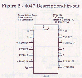
An Astable Multi-vibrator is just a technical term for something that continually switches from one state to another then back again i.e. it makes a square wave. The IC provides outputs Q and Q [Bar], ie. the output and it's . inverse. A resistor and capacitor are used to determine the frequency. T (the period of the waveform, 1/f) is related to the product RC. R is usually in Meg ohms (x1,000,000) and C in µF (x0.000,001) which luckily cancel each other out. I used R= 8.2M and C = lµF which give T = 8.2.seconds. If you increase the values of R and/or C the circuit slows down. A good analogy for this is a bucket of water being fed by a pipe. Every time the bucket fills up it triggers a change of stage and is emptied to start again. If the diameter of the pipe is increased (ie. reduce resistance) the water fills the bucket quicker, if the bucket is made bigger it takes longer to fill.
A 555 timer could also be used to make a square wave output but these require more discrete components and you have to get a special one whose logic levels comply with CMOS standards.
This IC's Q output can then be fed in to an 8 stage counter. The CMOS 4516 Binary Up/Down Counter can perform this function. It's pin-out looks like this:
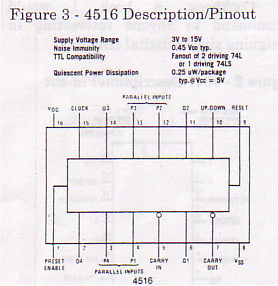
It actually cycles through 16 stages 0000-1111 binary, but that is just two lots of *000-* 111 ie. 0-7. DON'T use the CMOS 4510 Up/Down Counter as this only has 10 stages and would give 0-7, 0-1,0-7...
The IC has a reset line, this can be reset at start up using a capacitor and resistor in parallel to give a brief high pulse at power up, if you wanted a low pulse all you would have to do is reverse the position of the components. Pre-set inputs P1-P4 are set to 0000, this means the count will always start at stage 0 in this case, a minor detail here but more important in other types of digital circuits. The IC gives the following outputs:
| Stage | Q3 (4) | Q2 (2) | Q1 (1) |
|---|---|---|---|
| 0 | 0 | 0 | 0 |
| 1 | 0 | 0 | 1 |
| 2 | 0 | 1 | 0 |
| 3 | 0 | 1 | 1 |
| 4 | 1 | 0 | 0 |
| 5 | 1 | 0 | 1 |
| 6 | 1 | 1 | 0 |
| 7 | 1 | 1 | 1 |
0 stands for logic level 0 or Ov/Gnd and 1 stands for logic level one or the supply rail voltage (3v-15v for CMOS depending on which power level you choose to use, this means your circuit can be driven by a PP3 9V battery meaning you don't have to have a power supply).
Now let use combine the two tables, remembering to make the Red and Green states longer (3 times longer to be precise). For some reason it seems natural to start at Red:
| Stage | Q3 (4) | Q2 (2) | Q1 (1) | Red | Amber | Green |
|---|---|---|---|---|---|---|
| 0 | 0 | 0 | 0 | * | ||
| 1 | 0 | 0 | 1 | * | ||
| 2 | 0 | 1 | 0 | * | ||
| 3 | 0 | 1 | 1 | * | * | |
| 4 | 1 | 0 | 0 | * | ||
| 5 | 1 | 0 | 1 | * | ||
| 6 | 1 | 1 | 0 | * | ||
| 7 | 1 | 1 | 1 | * |
We can now derive the following logic equations from this table:
Red= NOT Q3
Amber = Q2 AND Q1
Green = Q3 AND ((NOT Q2) OR (NOT Ql) )
Gate Total = 6 gates of 3 types
Most people assume LED's have to be connected to the negative supply rail. This is true if you want them to activate on logic high, but if you want them to activate on logic low you can connect them to the high rail and sink them through the IC. So if we change the equation to negative active LED's we get:
NOT Red = NOT NOT Q3 = Q3
NOT Amber = NOT (Q2 AND Ql) = Q2 NAND Q1
NOT Green = NOT (Q3 AND ( (NOT Q2) AND (NOT Q1) ) ) = Q3 NAND (NOT Q2) OR (NOT Q1))
Gate Total = 5 gates of 3 types
But we are not finished. De Morgans laws state:
NOT (A AND B AND C...) = (NOT A) OR (NOT B) OR (NOT C) ...
NOT (A OR B OR C...) = (NOT A) AND (NOT B) AND (NOT C) ...
If you don't believe me draw up a few logic tables and try it out. What this law means basically is that you can convert OR's to AND's and AND's to OR's using the simple rules:
If it's a AND change it to an OR, if it's an OR change it to an AND. Invert all input and outputs.
So our ( (NOT Q2) AND (NOT Q1) ) becomes:
NOT ((NOT NOT Q2) AND (NOT NOT Q1)) = Q2 NAND Q1
finally giving:
NOT Red = Q3
NOT Amber = Q2 NAND Q1
NOT Green = Q3 NAND (Q2 NAND Q1)
Gate Total = 3 gates of 1 type
But as two gates are identical that means we only actually needs two 2-input NAND gates. So you can see many complicated logic equations can be boiled down to something a lot simpler with a little thought. I find this process most enjoyable. The gates are available on the CMOS 4011 Quad 2-Input NAND Gate IC. It's pin-out looks like this:
Figure 4 - 4011 Description/Pin-out
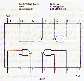
It is good practice to tie the inputs of unused gates to the nearest supply line otherwise their inputs will float causing increased switching which uses more power.
So here is the block diagram for the circuit:
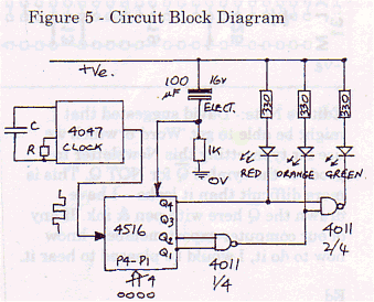
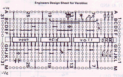
I made this circuit up on breadboard and tested it. The layout follows. I am also willing to supply kits of all the parts needed to build this project (with the exception of the breadboard and battery). But you can buy PP3 9V batteries in many places or use a power supply. I will be writing future articles about circuits you can build on breadboards, so it might be worth your while in buying one of your own if you don't have one, they are very useful for prototyping circuits (analogue and digital). I think the kit would be particularly useful to unskilled members who have difficulty identifying components. The kit consists of 3 IC's, 2 capacitors, 5 resistors, 3 LED's, wire links (please specify if you want these i.e. if you are going to build the circuit on breadboard) and a battery clip. The LED's have the resistors soldered on to them for convenience. The price is £4 including P&P.
If anyone builds this circuit on veroboard please send a layout to George Burton the Editor so he can include it in the next issue. One application for this circuit (using 3mm LED's) could by for traffic lights ' on models.
x1 lµF Ceramic Capacitor
x1 l00µF 16V Electrolytic Capacitor

x1 8.2M Resistor
x1 1K Resistor
x3 330R Resistor

x1 5mm Red LED (Light Emitting Diode)
x1 5mm Amber LED
x1 5mm Green LED

x1 CMOS 4011 IC - Quad 2-Input NAND Gate
x1 CMOS 4047 IC - Low-Power Monostable/Astable Multi-vibrator
x1 CMOS 4516 IC - Binary Up/Down Counter