Preamble
This is a simple receiver that can be built in a weekend. Do not be put off because of its simplicity as this is a very sensitive and selective receiver. It covers the HAM band (radio amateurs) on 160 metres, Morse code (CW) and single sideband (SSB) voice transmissions as well as the usual 'domestic' amplitude modulation (AM) radio programmes on the medium wave band. There is good sensitivity (gain) and selectivity (station separation) with this easy-to-build receiver.
General chat
The prototype receiver I built covers the frequencies 2.4mHz to 660kHz and covers all my local broadcast stations and the radio amateurs on Top Band (160 metres or 1.8 to 2 MHz.) The activity, ( the number of radio amateurs using Top Band is lower today than it used to be because of the increase of commercial equipment and the more flexibility of the bands (wavelengths allowed). At one time, when I first became interested in amateur radio, most of the radio equipment was homemade. This was not always by choice as it was expensive to buy ready-made equipment that could receive amateur transmissions as well as other types of communication such as trawler bands, shipping and aircraft. Amateur radio too was different in general as the radio amateur was an experimenter and a pioneer. The new comers to the world of amateur radio has had a lot of the donkey work done for him (or her) so some of the excitement has been taken away. However it does leave the door open for much more to be achieved that could not have been attainable in the early days. Morse code, the dots and dashes, usually referred to as CW transmission has now almost gone from the world of amateur radio operators. My stepgrandfather's brother ( with the amateur call-sign G6BK) was a CW only operator and his homemade transmitter took up one and a half walls of the spare bedroom. It was not always necessary to receive his transmission on dedicated equipment as it could also be picked up on the local broadcast receiver. The quality of transmission as far as suppression of interference is concerned has also improved. VHF frequencies were regarded as experimental and UHF was given to amateurs because it was thought of as useless for transmission purposes. Marconi was far ahead of his time in his day but he would be amazed at radio communication today.
Introduction to the receiver.
Amateur radio transmissions can still be heard on this `Top Band' section of the receiver and some SSB voice transmissions as well as CW. I logged over 30 stations one Saturday evening. My aerial system is about 20 feet high and about 30 feet long. I use quite a good earth which is essential. It is a copper rod buried about 3 feet into the soil outside the shack. I water it during the summer months.
The receiver uses just one transistor, a field effect type (FET.) with part number BF244. This is a common or garden type NFET and is available at low cost from Maplins. The output is of course low level and an audio preamplifier with an output stage should be used for headphones or speaker. Whilst tuning one evening over 30 stations were heard and I was again introduced to the fading of receiver stations which were once common during the Radio Luxembourg reception days. That is giving my age away!
The early days
The simplest radio receiver is the crystal receiver. It is a most insensitive design compared to todays receivers.
The crystal set of today would comprise a crystal diode (the modern equivalent of the 'cats' whisker.) with a pair of high impedance headphones. This can be reproduced with a tuned circuit and a high impedance input amplifier. The ONLY advantage of a crystal set is the fact that it does not use batteries which were expensive in the early days.
The present day.
The better modern day version of the crystal set is with the use of an N-FET type Field Effect Transistor. This uses the transistor as an amplifier as well as detector and the only addition is a battery.
The design of this receiver is actually from `the old days' and is a super-regenerative type where some of the signal is fed back into the input of the transistor via a small winding on the coil former which is used in this circuit which is a ferrite rod aerial.. This will put the circuit into oscillation if too much feedback is re-inserted into the input. So a variable capacitor on the feedback coil is used to reduce the amount of feedback. Feedback increases the gain to a very high level and careful adjustment is required so that it does not oscillate. It is easy to get the 'hang of it'.
The receiver circuit.
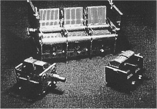
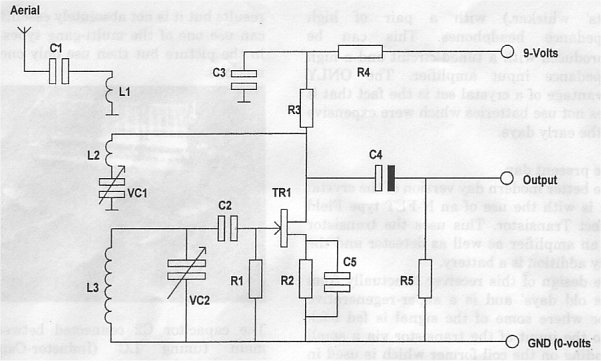
The coils are wound on a ferrite rod of about 130mm or longer. It can be obtained from an old transistor radio or even purchased from the suppliers. I got mine from an old radiogram (remember those!). There are three windings and they should all be in the same direction. The main coil (L3) has 60 turns, the feedback winding (L2) has 6 turns and the aerial (L1) has 5 turns. The wire can be about 27swg (0.4mm) diameter insulated copper wire. The capacitor in the aerial circuit is about 680pF and is there to increase selectivity as far as we are concerned. It can be left out with the aerial connected directly to the L1 but at a reduced selectivity performance. Na! Leave it in. The tuning capacitors used were obtained from scrap valve receiver but they can still be got from suppliers. The standard size is 500pF 0.0005uF for the main tuning (VC2) and around 150pF for the reaction(M) coil winding for the best results but it is not absolutely essential. You can use one of the multi-gang types shown in the picture but then use only one of the sections.
The capacitor C2 connected between the main tuning LC (Inductor-Capacitor) network is for dc (direct current) isolation and is 100pF. The Gate resistor (R1) is 1 Meg.Ohm (grid leak from valve theory.) The FET TR1 is an N-type BF244C. The source resistor R2 is 2k2 and its associated capacitor C5 is lOnF (O.OluF) ceramic type preferred. The drain resistor R3 is 1K2 and the decoupling capacitor, C4 is an electrolytic type and is lOuF at 16 volts working or higher.
The output can be connected to either high impedance headphones as in crystal set days or better, connected to an amplifier with a pre-amp stage incorporated. The circuit works from a PP3 type, 9 volt battery and draws very little current so a good battery will last a very long time. The radio needs a good aerial and a good earth ( not the mains earth because it introduces mains hum) for best results but for local reception, no aerial is required as the ferrite rod will act as a good universal aerial for local stations and for some distant ones too. Even without a good aerial, by connecting the earth to the aerial coil will give surprising results.
The complete receiver circuit.
This will need to be connected to high impedance headphones or better, to an amplifier with a pre-amp incorporated.
Parts List Rl l.megohm Ľ W. carbon or met. film R2 2k2 " " R3 1k2 " " R4 270ohm " " R5 10k " " C 1 680pf polystyrene or similar C2 100pf polystyrene or ceramic C3 1nF ceramic C4 lOµF 16 volt electrolytic VC1 150pf variable capacitor VC2 500pF variable capacitor TR1 BF244C FETConstruction
The construction is fairly straight forward but the coil assemblies need a little explanation.
The left hand side coil is the aerial coil. The middle coil is the main tuning coil and the right hand side coil is the reaction winding. It is not critical where they are placed, it just suited me to place them about 15mm apart. The windings are close wound. I used the original formers which were already on the ferrite rod after I removed the old copper wire.
The most important factors are rigid construction of the tuned circuits and short component leads. The connections from the coils to the tuning capacitor, the reaction winding and the FET should be stiff (18swg or better.) to eliminate drift due to movement. Short connections are also important.
In use.
This little receiver, when connected to an amplifier, aerial and earth can perform favourably compared with a commercial radio. Start with a low volume setting on the amplifier or you will upset the neighbours. When all is connected, tune for a station, if nothing is heard, tune the reaction capacitor until oscillation is heard. If this does not happen, reverse the wiring to the reaction coil as it may be the wrong way round. When you get oscillation, reduce the feedback until it just stops. Then try the tuning capacitor again. With a strong signal use less feedback. Log your stations, especially at night and you will be amazed at the number of stations that can be received.
Further experiments.
Build an amplifier with pre-amp into the receiver to make it self-contained.
Try changing the main coil windings, 80 or 100 turns for long waves (lower frequencies) or less turns, 40, 30, 20 or even less.) for ,shorter wavebands. Take care not to short any turns or you will not receive anything.
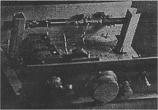
My prototype reciever showing the coil construction on a ferrite rod. It is built on a prototype chassis that I use for radio circuit designs. There are more controls on the front panal than are needed for the reciever described in this article. It is pictured here to show the coil windings.
The is an interesting little radio that is cheap and fun to buld. Have fun!