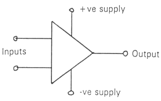
As can be seen it has two inputs and one output. The power supply connections are usually omitted from diagrams for simplicity. The op-amp often comes in an 8 pin DIL package with pin connections as below:
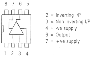
The commonest op-amp is the 741 or the 081 IC. The input labelled "+" is the non-inverting input and the "-" input is the inverting input. An op-amp wired in its simplest form is called a comparator, this is when the inputs are compared as the name suggests. Basically if the non-inverting input is at a higher voltage than the inverting input then the output will swing up to the +ve supply rail (which I will assume is +9v from the battery supply described in Part 1). Likewise if the inverting input is more positive than the negative input then the output will swing to the negative supply rail (or approximately there). You can try this out by using a potential divider to set the voltage at each of the two inputs at different levels and then checking what the output voltage is (make sure you have the leads of the voltmeter right way round to check each of the voltages). What the op-amp is doing is amplifying it by such a large amount (about 100,000 times) so that if the inputs were 1v different then the output should be 100,000 volts!!! But we only have a 9 volt supply so the upshot is that the output "saturates" at the voltage of the appropriate supply rail.
This is fine for comparing the voltage at the two inputs which is why the circuit is called a comparator but it is not much use as an amplifier. The way op-amps are used to amplify is by using a technique called negative feedback: this happens when the inverting input is connected in some way to the output terminal. The simplest form of negative feedback is when the inverting input is connected directly to the output. The input is then to the non-inverting input. Try this out for yourself, changing the input voltage and noting the output voltage. You should see that the output directly follows the input: this is called a Voltage Follower and is useful in the first stages of amplifiers where a microphone output needs to be amplified. The microphone can only supply very small currents at its inputs for larger current availability at the output - so the microphone output can now be fed into further amplifiers without degrading the signal.
The amplifiers to further amplify the signal can also be op-amps, this time in the negative feedback mode. There are two types of negative feedback op-amps called the non-inverting and the inverting. In the first one a fraction of the output is fed back to the inverting input and the amplified output follows the input which is applied to the "+" input.
In the inverting type the output is fed back to the "-" input and the op-amp inverts the signal as well as amplifying it. This is shown more clearly in the diagrams below.
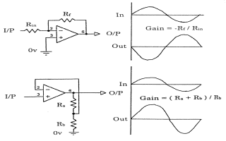
I will leave it up to you to experiment with these two amplifiers but please note that when using an inverting amplifier the input resistor will be the input impedance of the amplifier so as a rule of thumb keep it above 10k.