by M.A. Stracey Eng. Tech. (AMIEIE) G7LKJ.
Even with transistors, battery power is much more expensive than mains power, so most equipment is designed to be run off the AC mains, and battery operated equipment often has a mains unit built in to provide an alternative cheaper supply when portability is not a requirement.
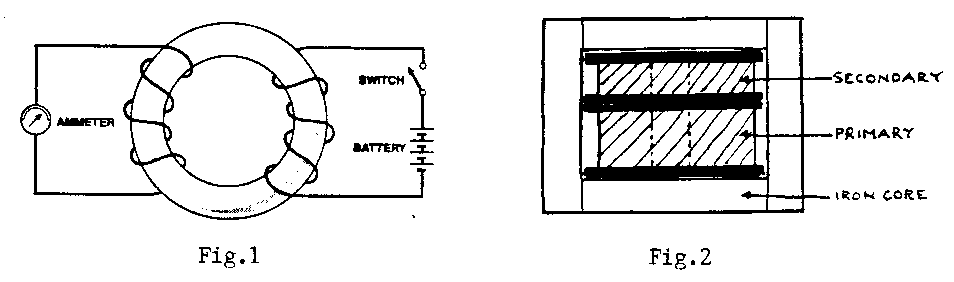
Most transistorised equipment operates on a low voltage, and to produce this from the 240V AC mains a transformer is used. This consists basically of two coils of wire wound on a bobbin through which an iron core passes. The principle on which the transformer works was discovered by Michael Faraday in 1831, and is called electromagnetic induction. He wound two coils on an iron ring, as shown in Fig. 1, and found that when the current through the primary coil was switched on, it caused a current to flow in the secondary coil. He was a bit surprised to find that when the primary current was switched off, a current flowed in the opposite direction through the secondary. So if an alternating current flows through a transformer primary it induces a corresponding current in the secondary. The ratio between the primary and secondary voltages is determined by the ratio of the number of turns on the two windings (the turns ratio). If the number of turns on the primary is ten times the number of secondary turns, the secondary voltage will be one tenth of the primary voltage - this is called a step-down transformer. If this turns ratio is reversed, we have a step-up transformer. The ratio between primary current and secondary current is the inverse of the turns ratio. To take a practical example, consider a transformer with a primary input at 240V and a secondary output of 6V at 1A. The ratio of primary to secondary turns will be 40:1, and in an ideal transformer of 100% efficiency the primary current would be 1/40A or 25mA. In practice, transformers have losses which reduce the efficiency to about 80%. Fig. 2 shows how a typical transformer is constructed.
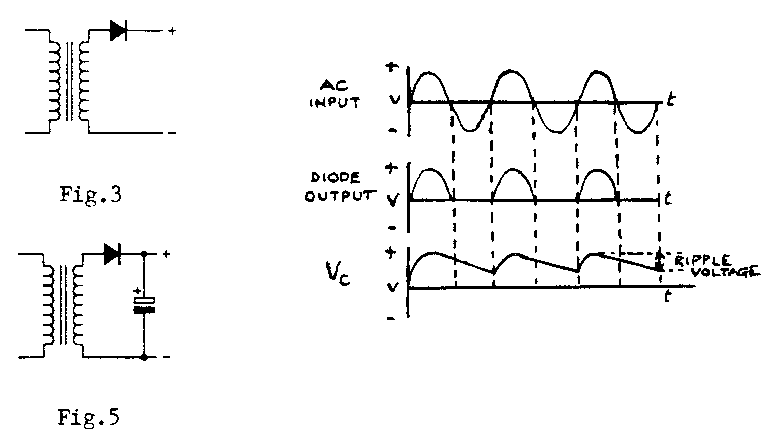
Most electronic equipment requires a DC supply. If a diode is connected in series with the transformer AC output (Fig. 3), a DC voltage is produced, as shown in Fig. 4. A diode used in this way is referred to as a rectifier. The diode conducts during the positive half cycles only, so the voltage output is only present for half the time. This is quite unsuitable for supplying power to equipment, so a large capacitor is connected across the output (Fig. 5). As the diode output voltage rises, the capacitor, which is known as the reservoir capacitor, is charged to the peak voltage. A perfect capacitor would hold this voltage, but all capacitors pass a leakage current, so the voltage drops until the next positive cycle charges the capacitor again. This voltage drop is called the ripple voltage; the circuit is referred to as a half-wave rectifier. It is inefficient, because half the transformer output is not used, and a large capacitor is needed to maintain the voltage between alternative half cycles.
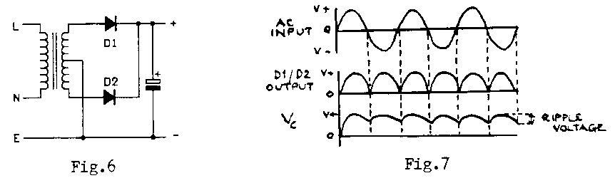
By using a transformer with a centre tapped secondary and a diode connected in series with each of the two ends of the winding (Fig. 6), both halves of each cycle are rectified; this is called full-wave rectification (Fig. 7). But this circuit requires a transformer with a secondary output voltage twice that of the previous circuit, so the efficiency is the same in each case, although the reservoir capacitor can be smaller. It should be noted that the output from both these circuits is equal to the peak AC voltage, which is 1.4 times the rated secondary output voltage. The ripple frequency is 50Hz in the half-wave circuit and 100Hz in the full-wave circuit. If the ripple is not reduced to a low level, DC supplies to audio equipment can introduce hum, and this is more audible at 100Hz than at 50 Hz.
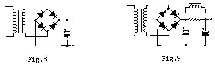
The most commonly used rectifier circuit is the bridge rectifier, which uses four diodes in the arrangement shown in Fig. 8. Only a single untapped transformer winding is needed, and the circuit is more efficient than either of the two previous ones. When point A goes positive, current flows through D2 and D3; on the next half cycle, A goes negative while B goes positive, and current flows through D4 and D1.
Choosing components for a simple unregulated power supply is straightforward. To start with the transformer: the secondary output voltage on full load must be equal to or slightly higher than the required DC output. If the output voltage is much higher there may be problems with regulation. The rated current output should be 50% higher than the maximum current to be drawn.
The bridge rectifier can be four similar diodes connected as in Fig. 8, or a single encapsulated bridge rectifier can be used. The latter has the advantage of being easier to install. The voltage rating of the rectifier should be at least three times the secondary output voltage. The reservoir capacitor should be a high capacity electrolytic with a voltage rating 1.5 times the secondary peak output voltage. The minimum value should be lpf for every 1mA output current, and a larger value is preferable. The maximum allowable ripple current of this capacitor must also be taken into account; if it is exceeded, the capacitor may heat up, which will shorten its life; also the amount of ripple may increase.
To reduce ripple in the output, some form of smoothing can be added to the basic circuit, as shown in Fig 9, where a resistor or inductor is inserted in the positive line, followed by another capacitor. The capacitor has a very high DC resistance but a low AC impedance, so the series resistor (or inductor) and the capacitor form a potential divider for AC in which most of the ripple voltage is dropped across the resistor (or inductor) and does not appear in the output. An inductor (choke) is more effective than a resistor because it has a low DC resistance but a much higher AC impedance. Nowadays it is more usual to use some form of electronic smoothing, which is more effective.
In dealing with equipment connected to the AC mains supply it is essential to remember that a short circuit can cause serious damage, and that mains voltage can kill. So take sensible precautions to avoid calamity. The equipment can be protected by fitting fuses of the correct rating in the right places. Standard 3- pin mains plugs have fuses fitted in them, but the smallest fuse normally fitted (and never supplied when you buy a new plug) has a 3A rating. This is far too high to protect the equipment, as the normal breakdown current for a fuse is 50 to 100% above the normal rating, so a fuse is usually fitted in series with the transformer primary. To find the correct rating, multiply the secondary output voltage by the maximum load current and divide the product by the primary voltage of 240V. So for a secondary output of 12V at 1A, the fuse rating will be 12 x 1= 240 = 0.05A i.e.50 mA. In practice, fuses rated lower than 100mA are fragile and expensive, and a 100mA fuse would be quite suitable. This will blow if either of the transformer windings develops a short circuit, but will not protect the transformer if a short occurs in the rest of the power supply, so it is quite common for a fuse to be fitted between the transformer secondary and the rectifier. The rating of this fuse should not be less than the maximum current to be drawn from the secondary. This fuse can be of the quick-blow type, but for the fuse in series with the primary it is preferable to use a slow-blow fuse which will withstand a momentary overload such as the current surge which may occur when the equipment is switched on. Fuses can be fitted in fully enclosed holders mounted on the equipment case, or in clips on the PCB. Make sure you observe polarity when fitting diodes and electrolytic capacitors. The working voltage of the reservoir capacitor should be at least equal to and preferably 50% higher than the peak output voltage of the transformer.
To ensure personal safety, particular care should be taken to ensure that all connections on the primary side of the transformer are soundly made. The incoming mains lead should pass through a rubber grommet in the case wall and be secured internally so that a pull cannot strain the internal connections, which are best made to a terminal block. If a mains switch is fitted it should either be a double pole type, or a single pole switch in the live mains lead. It is quite a good idea to fit a neon or LED indicator to show when the unit is live. If a metal case is used it should be earthed, but if a plastic case is used no earth connection is
necessary, and a two-core mains cable can be used. Incidentally, if you need to find out whether a connection is live, a neon screwdriver is the tool to use. But as a general rule no adjustment or measurement should be made in mains equipment unless it is first switched off at the mains socket to which it is connected. If you need to make a voltage or current measurement, fix at least one and preferably both of the test meter leads to the appropriate points with probe clips. If you use a test probe, make sure it is insulated to within a couple of millimetres of the tip. If a test probe slips off the point it is supposed to be in contact with it can cause damage if the equipment is live. There is a well known safety rule for
dealing with live mains equipment, which is to keep one hand in your pocket. But
that won't protect you if your body is effectively earthed, e.g. by standing on a
concrete floor. The best precaution is to understand what you are doing and switch
off at the mains socket before you start looking for faults.