As a background to this, gliders developed rapidly in Germany after the war ended in 1918. The Germans were prevented by the treaty of Versailles from developing military aircraft so they concentrated on gliders and in 1936 they produced a design which they proposed as the basis of competition in the Olympic Games; it was called the Olympia. Gliding did not make it as an Olympic sport but many Olympias are still flying, some in this country!
One German glider pilot flew in competitions in this country, his name was Kronfeld. Other pilots noticed that he was better than they were at finding thermals these are the rising currents of air which glider pilots use to climb and stay airbourne. They also noticed that he took a vacuum flask with him when he flew which had a tube coming from it. This was the basis of the first sensitive rate of climb meter or variometer.
As you know, atmospheric pressure falls as you climb higher. An altimeter uses this fact to measure altitude. It is simply an aneroid barometer with a scale in either feet or meters. If it were sensitive enough it could be used to indicate whether you were in a thermal but in fact it suffers from stiction and play in bearings and pilots often tap their altimeters to see if they really are climbing.
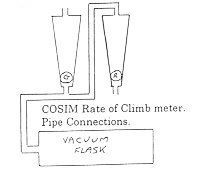
When a glider, is circling in a thermal it usually takes about 20 seconds to complete one full turn. If the pilot is only partly in the thermal he will have to say climb for about 5 seconds then sink for the other 15 seconds - any instrument to be of help to him in this situation therefore needs to have a response time of not more than two seconds. The first instrument to come close to this in the UK was made by a company called Cobb-Slater and was called a COSIM variometer. It was a flowmeter consisting of two tapered bore tubes of about 2mm bore connected in parallel to a vacuum flask with a tightly sealed bung through which the tube passed.
Diverting now slightly to the atmosphere so that we can get an idea of the magnitude of the air flow rate involved.
Pressure falls in the atmosphere as we go higher, at sea level it is about 1000 millibars: at 3000 meters it is about 700 mb and at 9000 meters it is about 300mb. In English units 3000 meters is about 10,000 feet so a third of the atmosphere is below you when you are at this altitude. These figures show that for a standard vacuum flask of 500 mls. with a tube through the bung almost one third of the air in it will have flowed out at 10,000 ft. This is 166mls. The pilot wants to detect a rate of climb of about 100 feet per minute, 10,000ft at 100ft/min. would take 100 minutes so the flow rate of air out of the flask is 166 divided by 100 or 1.66 mls per minute. Incidentally a vacuum flask is used to eliminate the effect of variations in the outside temperature.
The COSIM variometer easily detected this flow, one of the small pith balls in the tapered tube was coloured green for rising and the other was red for sinking. Since the tubes were connected in parallel the air caused one ball to rise in its tube when it was flowing out and the other to rise when it was flowing in. Its major disadvantages were a sensitivity to moisture on the walls of the tubes and the dead volume of the tubes themselves which meant that this amount of air had to be displaced before the other ball could indicate.
The first of the thermistor variometers to appear in the late 50s was again made by Cobb-Slater and was designed by an engineer called Cook, hence it was the Cook Variometer. It used two miniature naked bead thermistors in close proximity to each other so that one was cooled more than the other in the flow of air from a large two litre flask. They were connected as two arms of a Wheatstone Bridge with two fixed resistors, a battery supply and a sensitive microampmeter detecting the unbalance. It was very non linear because with the large amount of air (relatively) flowing, both thermistors rapidly approached the same temperature as each other and the bridge unbalance decreased. I used the same basic layout of the thermistors but instead of expensive American Fenwafl bead thermistors I used a relatively cheap Mullard type, the VA3102. Its disadvantage was that it was larger and so had a longer time constant of about four seconds but this was overcome by operating them at constant temperature in a feedback circuit and hence the physical time constant of the thermistor virtually disappeared and one measured the current unbalance necessary to maintain their temperature constant. The actual operating temperature was about 175 deg. centigrade which may seem high but it had to be well away from the air temperature so that the effects of varying ambient temperature were minimised. They were good and stable and many are still in use 25 years later.
When they were used to measure the gas flow in a Gas Chromatograph there were two main differences: first the flow was unidirectional so only one thermistor was needed, secondly the gas used was usually Helium and because it is a light gas it has a very much higher thermal conductivity so that much more power was needed to maintain the thermistors at a fixed temperature.
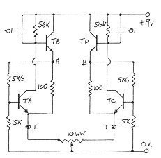
Constant Temperature Thermistor Bridge Circuit
The base - emitter junctions of transistors TA and TC are connected across the bridge circuits consisting of the 5K6, 15K , 100R and the thermistors T. The collectors of TA and TC drive the bases of TB and TD in such a manner that the bridges are kept in balance (The resistance of the thermistors falls as they get hotter). The 10R wirewound pot is for zeroing. The output is taken from points A and B.