The simple power supplies described in the last part of this series give an unregulated output; the output voltage is high when the current drawn is small, and drops as the output current increases. This may not matter in some applications, but in most cases a constant voltage independent of current output is required. To achieve this, some form of regulation must be provided.. This article will deal with the simpler types of regulator circuit using diodes and transistors, which provide a useful degree of regulation. The next article will deal with regulator ICs, which are more effective as well as simpler to use.
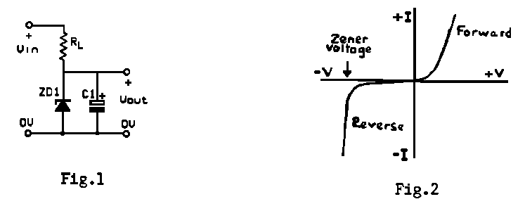
The simplest type of voltage regulator is the zener diode, and the method of using it is shown in Fig. 1. The voltage rating of the zener diode is chosen to be equal to the required output voltage. At input voltages below the zener voltage, the resistance of the diode is high; when the input voltage rises above the zener rating, the resistance of the diode falls sharply, and the current through it rises rapidly (Fig. 2). To limit this current a resistance RL is placed in series with the diode, as shown in Fig. 1. One drawback is that zener diodes generate a lot of electrical noise, and although in many cases this will present no problem, it is a good idea to put a decoupling capacitor across the diode. Diodes with low voltage ratings show lower stability in response to variations in input voltage.
Most zener diodes have type numbers which begin with BZ, followed by a third letter (V, W, X, Y or Z) and a number indicating the wattage dissipation of the diode, then the voltage rating of the diode. For example, a diode marked BZY88C5V6 is a 5.6V zener diode of the BZY88 series, which has a wattage rating of 400mW. The letter C before the voltage rating indicates 5% tolerance. Some zener diodes have numbers beginning 1N; these are not marked with the voltage rating.

As an example of the use of the simple circuit shown in Fig. 1 to give a 10V 100mA regulated supply from a supply voltage of 20V, a zener diode with a rating of 10V is used, and the series resistor RL has to pass the supply current of 100mA plus 5 to 10mA through the diode. A resistor of 91 ohms will give the required 10V drop plus 10mA through the zener diode. The power dissipated in the zener diode in these circumstances would be only 10 x 0.01 watts, i.e. 100mW. A 400mW; zener diode could be used, but if the current drawn from the supply is likely to fall, the current through the diode will rise, and in the extreme case where the supply current drops to zero, the whole current of 110mA would pass through the zener diode. If this is likely to happen, the zener diode would have to be rated at 10 x .11 watts, i.e. 1.1 watt. The next higher rating of commonly available zener diodes is 1.3 watts, so one of these would have to be used. In practice, simple zener diode regulators are normally used only when the output current is small and not likely to vary much.
A better way to use a zener diode to produce a regulated voltage is to use it in conjunction with a transistor connected as an emitter follower. This circuit, shown in Fig. 3, is known as a series regulator, and the transistor is often called a pass transistor. The current through the zener diode is no longer dependent on the load current, and the resistor R1 in series with it is given a value which will produce the required 5 - 10mA through the diode. The voltage output from the regulator is controlled by the base voltage of the transistor, which is held constant by the zener diode. Provided that the input voltage is greater than the required output voltage, variations in the input voltage or changes in load current will not affect the output voltage. Since 0.6V is needed to turn the transistor on, the voltage rating of the zener diode has to be 0.6V higher than the required output voltage. 400mW zener diodes are available in voltage steps corresponding to the E24 resistor values; the lowest rating being 2.7V. For a 10V supply the nearest would be an 11V rating, which would give an output of about 10.4V. Alternatively, since zener diodes can be connected in series to give a desired voltage rating, one could use two with ratings of 5.1V and 5.6V in series, which should give an output nearer to 10V. But note that the tolerance of these zener diodes is 5%. The type of pass transistor used depends on the load current, and should always have a collector current rating several times the required output current. If this is high, the transistor must have a heat sink. The transistor provides current gain, so the emitter output current can be far higher than the input current to the base. The higher the transistor gain, the better the regulation, so in practice two or even three transistors in Darlington connection may be used, as shown in Figs. 4 and 5. When using more than one transistor, the voltage drop is 0.6V multiplied by the number of transistors. Only the final transistor has to be rated to pass the full load current.

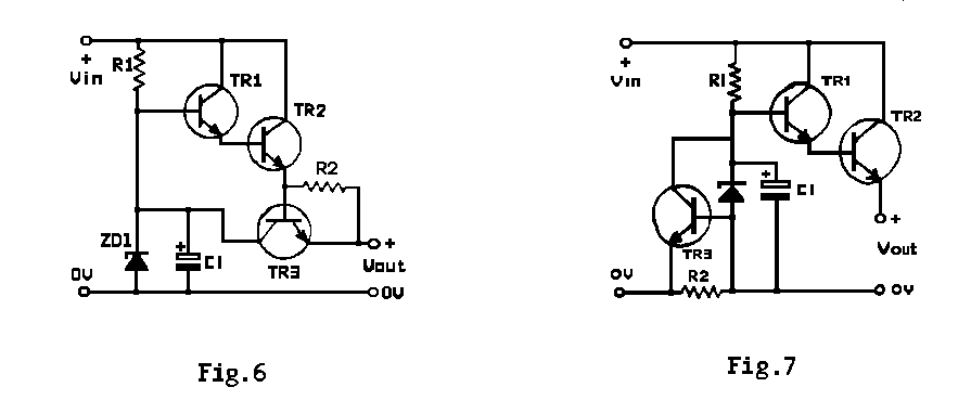
It is usual to include some form of current limiting to safeguard the regulator against short circuits, and a simple way of doing this is shown in Fig. 6, which includes a resistor R2 in series with the output and a transistor Tr3 connected across the regulator. The value of R3 is chosen so that at full rated output the voltage developed across it is just below the 0.6V needed to turn Tr3 on. If the current rises above this level, Tr3 begins to conduct, diverting some of the input current for TR1 to the negative supply rail via the load, so reducing the output voltage. Any further increase in output current will increase the voltage across R2, driving Tr3 harder into conduction and reducing the output voltage still more. If the output is short circuited, the output voltage falls almost to zero, and the output current rises only to a small extent. One disadvantage of this arrangement is that R2 produces a drop of about 0.6V in the output. This can be overcome by putting R2 in the negative supply line and connecting the transistor across the zener diode, as in Fig. 7.
