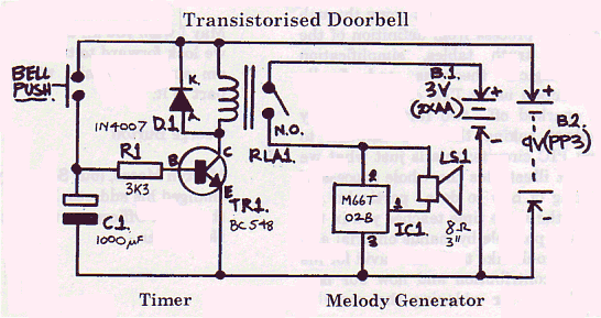
There was a typical sample circuit in the catalogue so I built it to this circuit and I found that the volume was high enough but the silicon chip played continuously as long as the supply was maintained. The problem was how was I going to get that to be a doorbell? A lazy way of doing it would be to put the bell push in series with the battery supply but since most people press a bell push in the same way that they press the keys on a computer keyboard, this would only give one or two notes of the melody so I decided that a timer circuit was needed which would trigger when the push switch was operated and would hold the circuit on for the few seconds of the tune.

I looked through the junk box again where I got the loudspeaker from and found a 1000µf electrolytic capacitor which would hold its charge for a few seconds and keep the relay RLA1 operated for the time of the tune. The relay needed 9 volts at low current but the loudspeaker circuit needed only 3 volts at a higher current so I decided to have separate batteries to operate the different parts of the circuit. Also if the transistor switches the current to the IC directly it gives an odd effect at the end of the tune as if the musician playing it had been shot and was still trying to play it as he collapsed.
My uncle drew out the schematic for me because my own attempt was a bit too messy to reproduce. The full circuit is shown below. The diode D1 is to protect TR1 from the high voltages produced when the current in the relay coil is switched off and the coil magnetic field collapses.
(A very creditable effort, Mickey, even if your uncle did help a bit. Ed.)