Following the collection of circuit blocks which formed the motor drive controller in the last issue, the section we can now turn our attention to is the preset timer/display module that was represented as an unexpanded block in part 11, Fig. 5. It should first be understood that the circuit described here has not yet been built and tested. It is therefore an initial designers drawing with support networks configured for the purpose it was designed to serve, and connected with reference to the device data and applications sheets. One of the main features of the design is its battery back-up facility which is required to retain count and register information when switched off. Others are its protection against accidental reset in back-up mode by using an indirect reset network, and its simple output selector which is automatically switched by the count direction input level. Apart from this, the circuit is a standard presettable counter/display module which can be used in a variety of applications.
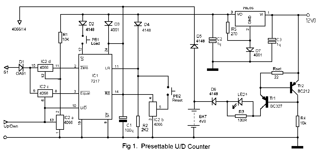
The central component in this circuit is the 28 pin ICM7217AIPI presettable decade counter for driving a four digit, common cathode 7 segment display. A four digit, true binary thumbwheel switch is used to set a target figure for an up-count, whereby an "equal" output changes state when the target is reached. In this operation, a register is loaded (LR=1) with the number on the thumbwheel switches and is then continuously compared with the incrementing number in the counter. The "equal" output switches low when the number in the counter has reached the number in the register. The display in this mode will start at zero and will show the same number as the thumbwheel switches on completion of the count. Further count operations to the same number are achieved by resetting the counter (RS=O). A down-count from any preset number up to 9999 can be carried out by loading the counter (LC=1) with the number set on the thumbwheel switches, whereby the counter will count down from this and switch the "zero" output low on completion of the count. In this operation, the display will immediately show the preset number when LC is taken high, and will decrement with the count until zero is reached. Further down counts are initiated by pulsing LC high. Having now some idea of its operation, we can look at the circuit of Fig. 1.
With more than half the 28 pins of the 7217 reserved for display driving and data loading, we can simplify the general approach to this design by first looking at the main control pins relative to what we already know about device operation Configuring these pins is the main consideration in this application as the rest are standard data sheet connections for virtually all designs. Each control pin is tri-state and set to mid supply voltage by an internal resistive voltage divider. Leaving any pin open results in normal operation so we can look at each pin in turn, identify what functions they perform at each rail level, and then connect each one for the function we require.
Pin 12 is the Load Counter input; when pulsed high, it loads the value on the thumbwheel switches into the counter in preparation for a down-count; when taken low, the display is switched off. Pin 12 is therefore left open circuit for normal operation but connects to Vdd via a push-switch for loading the counter prior to a down count. Pin 11 is the Load Register input. When pulsed high, the number on the thumbwheel switches is loaded into the register as the target for an up-count; when taken low, the display is turned off. We shall need the register reading the same value as the thumbwheel switches at all times so pin 11 is tied permanently high. We need to use steering diodes to isolate the working and back-up supplies so Pins 11 and 12 connect via D2 and D4 to prevent them going too far above the voltage at pin 24 and imposing stress on the device. We can also see that either pin 11 or 12 will have to be pulled low in back-up mode to switch off the display for extended battery life. LR is chosen for this task because it is always high during normal operation whilst LC must be left to float R2 is therefore connected to LR and has no effect on the working high level but, as its value is considerable less than the input resistance of the device, it will pull this input low in the absence of a working supply, thus switching off the display Pin 14 is the Reset; when pulsed low, both counter and register are reset to zero; when either high or open. normal operation is enabled. Reset could be switched to ground via a push-button but this could cause loss of data by an accidental reset in battery back-up mode. Pin 14 is therefore grounded via IC2b when PB2 is closed during a valid reset operation but as there would be no supply to PB2 in back-up mode, R2 will hold the switch fully off ensuring that no false reset can occur. Note that, in this design, the register is immediately reloaded after a reset but the counter remains at zero. Pin 9 is the Store input; when low, data
from the internal latches updates the display; when high or open, the latches are disabled and the display will not be continuously updated. In some applications it could be desirable to strobe this input so the display would be updated at the completion of a count. Such an update signal could be taken from the active low output of the circuit via an RC differentiator. It was not considered necessary in this case so pin 9 is simply tied low to enable a permanent display update. Pin 10 is the up/dwn count direction control. The counter counts up when this is high and down when it is low. Since the count direction dictates which of the two outputs the end signal should be taken from, the level at pin 10 can also be used to select one of these outputs, hence, the electronic switch configuration at pins 2 and 3. When pin 10 is high for an up-count, switch C control is high connecting the equal signal to the output, switch A is closed pulling its junction with RI low, so switch D will isolate the Zero output. On a down-count, switch C will be off isolating the equal output, switch A will be off, its junction with RI will be high connecting the zero signal to the count output The electronic switch configuration therefore selects the appropriate signal for the target the counter is moving towards. DI is a blocking diode which prevents high level leakage current from flowing through into the adjoining circuit when the main supply is switched off The remainder of the circuit is a simple two transistor constant current generator used to charge a pack of four I V2 Ni-Cad cells. Charge current is set by the voltage drop across Tr2 emitter junction and the value of Rset, and is around 30mA in this case. It can be adjusted to suite the type of battery chosen for the back-up duration required; AA, C or D type. LED 1 is a charge current indicator. It is not capable of passing all the charge current alone so R3 shunts excess current past the LED. The value of R3 must be recalculated if charge current is increased and this is simply done using the formula, R = Vied / Ich - 15mA. The regulator is fairly standard except that D7 is used to jack up the common reference and therefore compensate to some extent for the drop across D3. R5 ensures that enough current flows through D7 to develop at least 700mV.
Fig. 2 illustrates the method of connecting the display and thumbwheel switches. The display comprises four low current, common cathode 7 segment digits with their anodes (a to g) connected in series for multiplex operation. In other words, all "a" segment inputs are wired together as are "b" etc... and connect to the segment outputs of the 7217. The Digit outputs, pins 15 to 18, then scan the four display common pins, from MSD to LSD, pulling each low in turn as digit information is sequentially loaded onto the 7 line segment bus. The number on the display is always equal to the contents of the counter and it is this number that will be compared with the contents of the register each time the display is updated
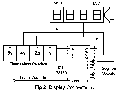
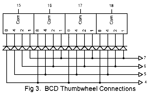
Fig. 3 shows how each switch connects to the register input bus via steering diodes so that they are isolated from each other. Since we know that our LR pin is permanently high, we can see that the thumbwheel switches will be continuously loading the register with the same number. This is neither here nor there in normal operation as comparison of the counter and register contents is executed internally. On an up-count, the counter will increment towards the thumbwheel number and will activate the equal output as soon as all four numbers loaded into the data port coincide with the four digits on the display. On a down-count, the LC input is pulsed high and initiates a counter load sequence whereby the digit outputs execute a full scan across the thumbwheel commons and loads this into the counter via the data port. Since LC is taken high only momentarily, this number remains latched into the counter; immediately appears on the display, and thereafter, the thumbwheel switches will serve no other purpose because the register contents are not required for a down-count. The counter will then count down in response to pulses at the count input (pin 8) and will activate the zero output when the counter contents reach 0000.
The counter IC described here is the Harris AIPI decade type which counts up or down from 9999. Type CIPI has the same pin-out as the former but counts up or down from 5959. It would therefore be the obvious choice for timing applications. As with all designs at this stage, there can be no guarantee that a few bugs will not crop up after construction, but that is the nature of electronic circuit development.
I would be more than happy to assist further if anyone tries building this circuit.