Mohammeds replies:- Your idea of using the type of Vero Board without copper tracks where you insert terminal pins to solder to is a possibility.
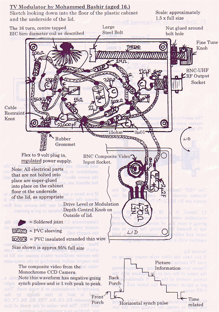
I used a cheaper approach which is sometimes called a Christmas Tree Construction.
With this the wire leads of the components are cut, bent and soldered together without any kind of board using sleeving to prevent shorting and adding wire where the leads were too short. Another name is `birds nest'. Of course this alone would be too flimsy and would cause frequency drift but if you then super-glue the components and wires to the floor of the plastic cabinet the assembly is made rigid and stable enough. You may have seen the VHF front end of a cheap FM radio almost enclosed in wax - this is the same sort of idea.
It is a good idea to glue the components down oriented so you can still read the part numbers and capacitor values and I recommend using a brand of super-glue which does not `bloom' or you can't see through it. You should check the glue by gluing two bits of scrap plastic together in the morning and then seeing if it is still clear in the evening.
Stray Broadcast Signal.
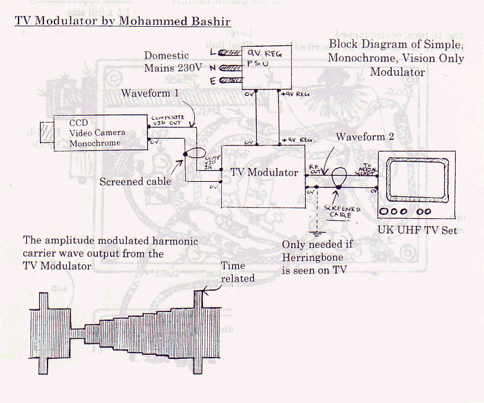
The circuit is unlikely to interfere with a neighbour's TV set as the UHF harmonics are not that strong. You only need a few millivolts of UHF RF voltage at the input of a TV set to get a good clear picture with no noticeable grain. The lead going from the modulator to the TV set is screened as is the lead at the input to your neighbours TV set so is unlikely to pick any stray signal from the modulator. I did have a problem with Herringbone patterning at first but I did not have to resort to a metal box. A connection between the Ov-rail and a radiator pipe cured the problem. The earth wiring was picking up a broadcast signal which was beating with the wanted RF from the modulator.
Operating Principle and TV Broadcast Bands.
The basic operating principle is that the fundamental operating frequency is a VHF signal but it is heavily clipped so the resultant waveform has a UHF content to which the TV set can be tuned. I don't know what the fundamental frequency is because I do not have an instrument which could measure or display that waveform. As a student I don't yet have an income to purchase such equipment. The VHF bands are no longer used for television in this country. The UHF range over which current TV sets tune are bands four and five which are approximately 470-585 MHz and 612852 MHz and I guess the harmonic which I tuned to was at the 470 MHz end.
Power Supply.
I used one of the power supplies which looks like a 13A plug with a small switch which you can select the output voltage. I used the 9 volt setting. You could build your own using a transformer, rectifier and regulating chip with smoothing. I am very shy of messing about with the mains because I received a severe shock when I was only trying to change a light bulb back in my home country of Bangladesh. The quality of the mains wiring was not very good.
Construction.
I enclose a detailed sketch of the project which shows the exact construction. I must point out that the head of the bolt which is used for tuning the unit is more facing the open end of the coil than shown. I drew it that way for clarity. There was no label on the reel of wire that I used so I enclose a small sample. (About 22thou dia. Ed.)


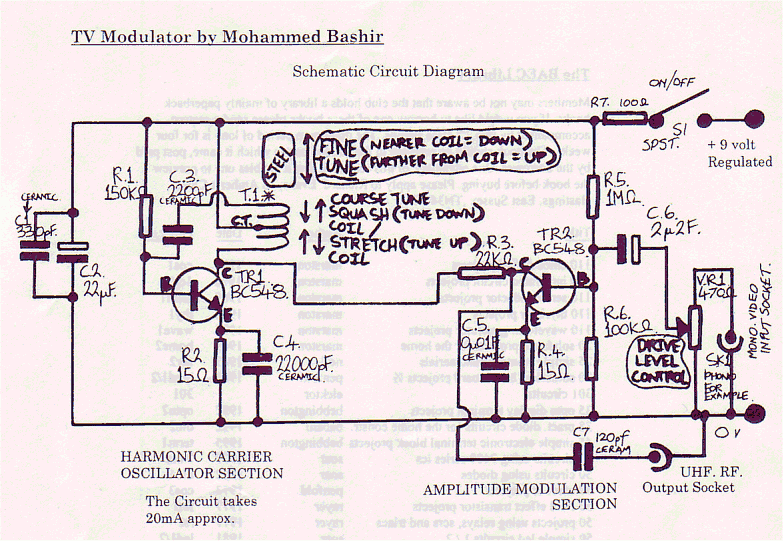
The VHF Oscillator is a version of the Hartley circuit. The components of the circuit are R1.R2.C3.C4.Tr1 and T1.
Tl Detail. It is 16 turns of 22 thou. enamelled wire wound round a BIC pen giving a turn dia. of about 8mm. A centre tap is formed by twisting the wire at one point and soldering a connection. It is held together with a cable tie and super glue.
Setting Up
If you have the older style rotary tuning on your TV tuning is easy.
Coarse tuning is stretching or compressing the turns of the coil in conjunction with the tuning control of the TV. It should easy to get a signal tuned to the lower end of the UHF range.
With the electronic sweep type of TV tuning you have to sweep the tuning over the low end of the UHF range as the coarse tuning and finally use the fine tuning screw of the modulator to get it accurately tuned. Note the screw should be brought nearer the coil but should not actually enter it.
If you have a set which simply allows you to choose the channels then you should set it to channel 22 and use the coarse and fine tuning of the modulator to get a picture.
Components C1, C2 and R7 de-couple the supply preventing unwanted modulation on the supply rail.
Next comes the amplitude modulation which simply adjusts the level of RF from the carrier oscillator which passes via R3 to the output socket according to the composite video input.
Unlike Audio Modulation of a RF signal, a Video Modulator must give the right polarity of modulation or it wont work. This need is met in this design by the components R3, C5, R4, TR2, R5, R6, C7, C6 and VR1. The low value of the track of this pot. doubles as a terminating resistor.
