[Oct10] PC1512 Interface Card

The Amstrad PC1512 was the first cheap mass market Personal Computer to come out in the UK in 1986. As opposed to microcomputers which ran games and the BASIC programming language. It had 512K of memory, two 330Kbyte disk drives and a monochrome monitor. With options for a colour monitor and 20Mbyte hard disk drive. It could run programming languages like Pascal, and games like Elite, Chess, Text adventures... and had a primitive windows desktop and mouse system.

It also had three expansion card slots.

Please note plug in and remove card when the computer is turned of to avoid short circuits. It is advisable to use an old out of data computer to run this card.

Address Card

I built the Card below using circuit transfers, a UV box and etching chemicals, plus a PCB (printed circuit board) drill. The PCB is double sided and fits in a 31-way on the computer's mother board. It has a 20 way DIL (dual in line) connector with ribbon cable to dock with the Input/Output and Analgoue to Digital units below. I also drove a speech syntesizer, 2-line 20 character LCD Display, 4 x 4 Character Starburst display, and stepper motor.

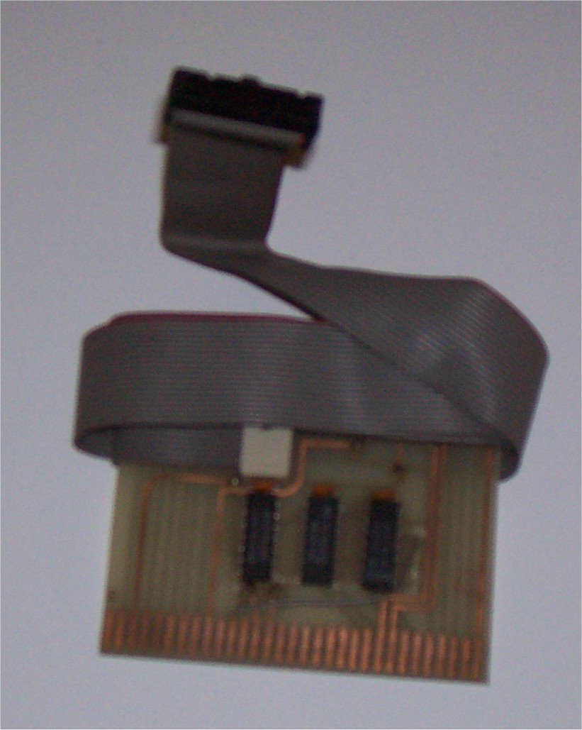
It addresses PC prototype hexadecimal address &300 for data and &301 for control using Pascals Input/Output binary command Port. It uses 3 SSI (small scale intergration) IC's: 74LS32, 74LS30, and 74LS14. With 3 10 Nano Farod ceramic capacitors.

Note: "The Master IC Cookbook" available from amazon.co.uk lists all TTL and CMOS Logic IC's used by this Interface System.

Address Card

IC's go in on top in Side B thus:
- B
-
-
- 74LS32 + 104 ceramic capacitor + width 5 x 4 height diagonal ribbon cable connector
-
- 74LS30 + 104       "
-
- 74LS14 + 104       "
-
-
-
Some through pin connectors are required as well.
PC Inteface Card - Side A Transparency: PC Interface Card - Side B Transparency
Pinout connections:
D0-D7, RD (negative logic pulse), WR (negative logic)
A0-A4, Interrupt 4, Interrupt 5, 12V, 5V, 0V

The Read line can activate the input channel reading what ever number is of the data bus (D0-D7).
The Write line activates a latch the writes data to the latch IC so it can display LED's for example.

Input/Output Module

This Input/Output Module has a 8-bit input channel, 8-bit output channel, x6 input control lines U-Z, and x6 output control lines A-F. 12V + 0V, Interrupt lines 4 + 5, and 5V and 0V. Wire is connected to them using terminal blocks.

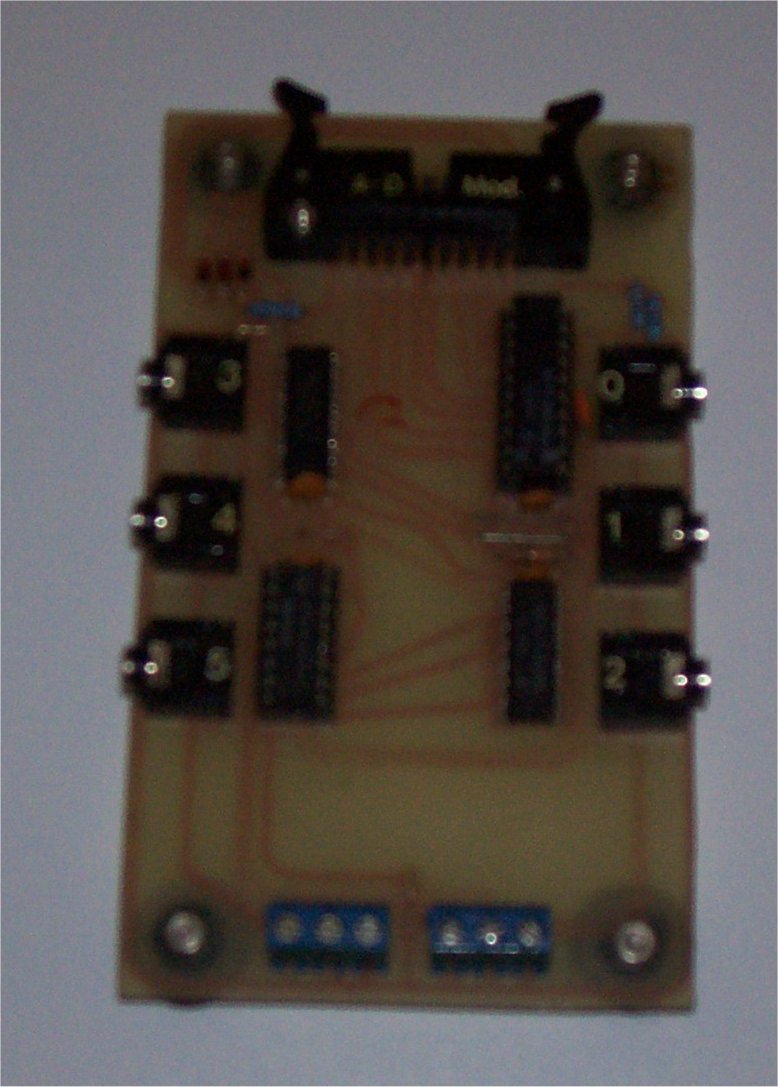
The module uses IC 74LS138 to decode the 5-line x32 module addresses plus 3 1N4148 diode, 1 1K resistor diode clamp logic. It has input latches 74LS244 and 74HC367, and output latches 74LS273 and 74LS174. It also has a R-C reset of 1K and 100µF resitor and capacitor so the output latches are at 0. The chips have 4 10 Nano Farod ceramic capacitors assoiated with them.
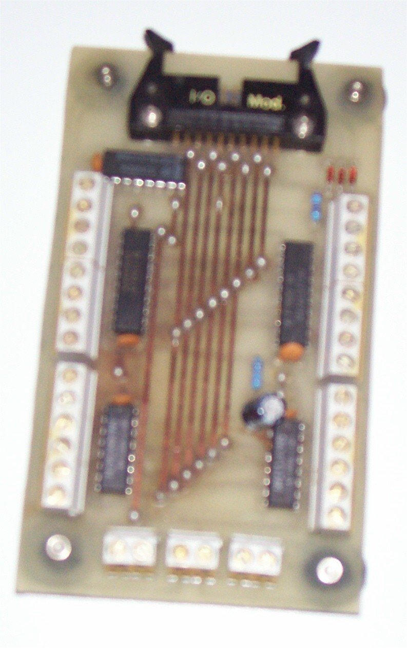
Input/Output Board

I/O Module - Side A Transparency: I/O Module Card - Side B Transparency

Analogue to Digital Board

This unit has x6 Analogue to Digital channels. Using 8-bit A/D chip ADC0804LCN with RC driver, 74LS174, 74LS138, and 74HC40611. There are also 4 10 Nano Farod ceramic capacitors, and diode clamp address decoding logic.

Analogue/Digitail Board

Driver Pascal Programmes

Interface ZIP File 123Kbytes
Includes .PAS and .COM files: AD_demo, IO_demo, motor, alpha, and batch files to run a menu under the MS-DOS operating system.