Diode-Clamp IC Technology???? Replace Transistors with Diodes for Logic Gates!
I read a text once about how you can make logic gates by using 2 diodes and a resistor which utilize the 0.6V drop across the diode to clamp the voltage to near 0V. LED's have a 1.2V drop across them.
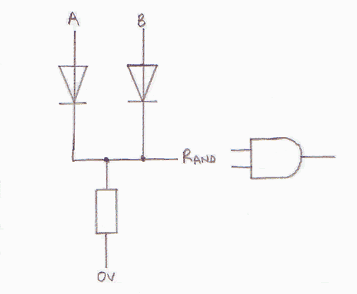
The following logic gates can be made (for one level deep logic at least, they use up less space that a x4 logic gate chip):
- NOT gate: Vcc -> Resistor -> Vout -> x1 Diode that sinks to -> Input A???? I'm not (to use a pune) sure if this works.
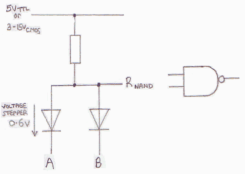
- NAND gate: Vcc -> Resistor -> Vout -> x2 Diodes that sink to -> Inputs A and B. If either input is 0V (logic 0) then the diodes 0.6V voltage drop forces Vout to be 0.6V by-passing the resistor which otherwise would supply Vcc -> Vout.
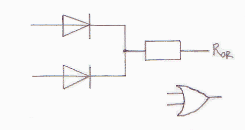
- OR: Inputs A and B -> x2 Diodes that sink to -> Vout -> Resistor -> Gnd. If either input is at Vcc (logic 1) they pull Vout up the Vcc - 0.6V (logic 1 also).
- The NOR, XOR (exclusive OR) and XNOR gates are not possible to construct. It's all a bit confusing! But you get the general idea.
This type of gate works in singular instances because I have used it on breadboards and circuit boards. I'm not sure if can works at the speed of IC's though.
TTL chip technology uses a transistor and resistor combination, and CMOS (Complementary MOS) uses NPN and PNP apposite each other linking between +V (3-15V) and 0V. Basically when one is on, the other is off, thus using less power. As you only use power when switching the transistor not burn up power on the resistor all the time. That's why they are used in clock circuit as the batteries last longer.
Why can't they make chips using Diodes, NP only???? This would take up less space and presumably use less power. One point is 'Diode-Clamp' technology can't form one type of logic gate. Another is that the drop of 0.6V accumulates with additional gates. Most processors use big addressing lines that require multiple levels of logic gate. But at a certain depth you could convert back to Transistors. Perhaps the chip might be more susceptible to static damage? I don't know if this is true.
Probably you would need at least 14.5 Volt to allow for bigger voltage drops. PC's only have 5V and 12V. This could link into CMOS (max. 15V). Chips are formed of four or more layers: P, N, P, and Resistor, so a normal chip screen could be used mixing Diodes and Transistors. The unwanted layers are simply etched away.


