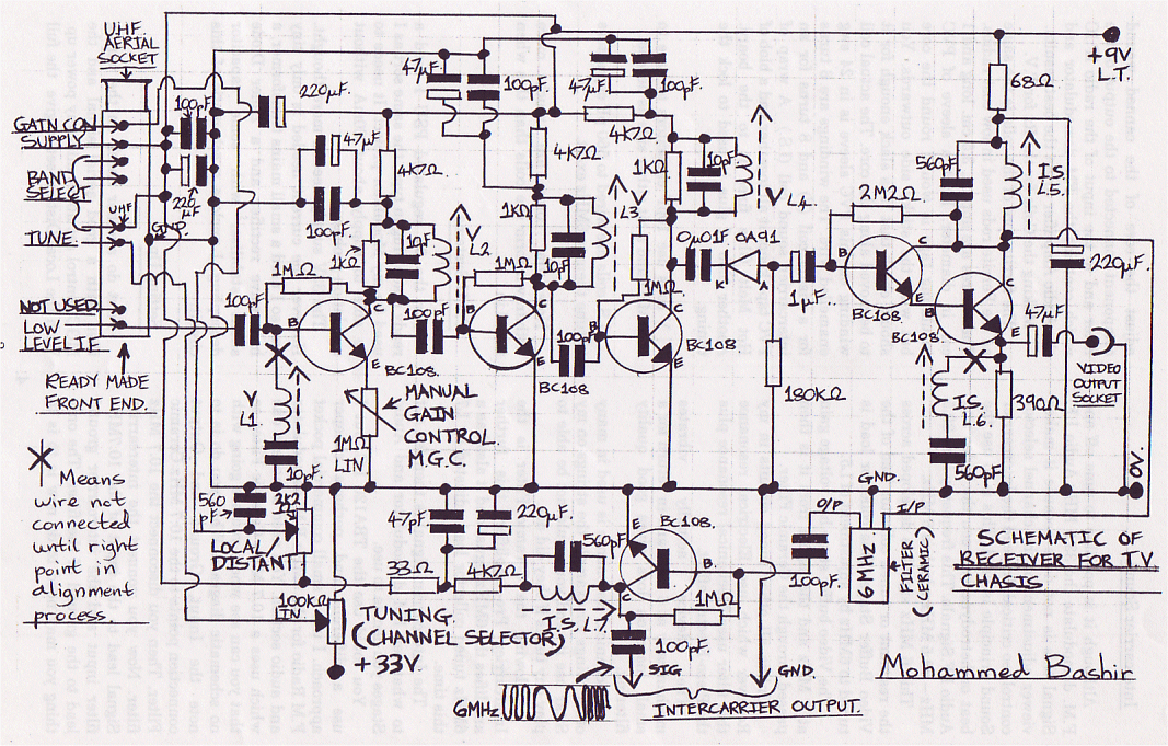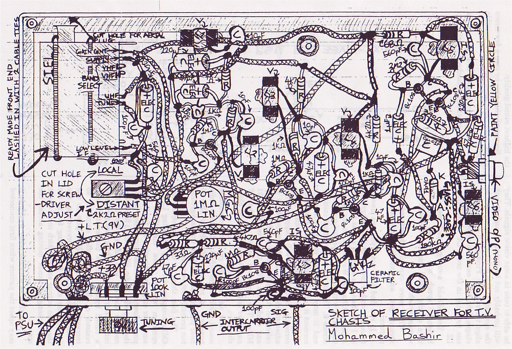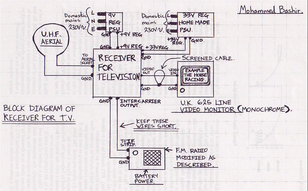
The circuit is designed to allow the reception of TV signals, picture and sound on a CCTV monochrome video monitor such as is used for example to monitor the signals from an intruder alarm camera.
Construction
The circuit was constructed on a piece of matrix board with holes on a .1 inch grid designed to accept push-in circuit pins. The board is cut to fit into the plastic box which is approximately 11 x 7 x 3 inches allowing room at one end for the UHF tuner. Pins are pushed into the matrix board as necessary.
PVC covered, single core, tinned copper wire is used for the wiring where necessary and when component leads are exposed PVC sleeving is pushed onto them to prevent inadvertent shorts.
The front end which I used was made by SIEL, the type number is 02586271 - 920775 - 00 - F2477 - 04. You can use any UHF front end even one of the older mechanical tuning type and then you would not need the +33 volt supply for the channel selector potentiometer.
The I.F.Strip
The Video and Audio IF signals from the front end are at 39.5 MHz video and 33.5 MHz audio (F.M.) These signals are both at low level. Taking the Video one first then, it needs amplification before it can drive the A.M.demodulator and this is done with three stages of transistor amplification. The most important thing with this amplification is that it should have enough bandwidth to pass the signal through without loss of quality. My design uses two methods for getting this bandwidth, these are:-
Control over the I.F.gain is manual in my design (MGC), this is mostly for simplicity but also for my own preference. The control is simply a variable resistor in series with the emitter lead of the first I.F. amplifier transistor. The effect of setting it too high is to give just silhouette images due to crushing in the overdrive plus a lot of noise (grain.)
Setting it too low causes a reduction in contrast. I chose to have the control knob for this on the underside of the cabinet because I found it did not need adjusting very often.
A.M.Video Demodulator
This could not be any simpler. It is just an OA91 diode and a load resistor.
It works of course by simply passing current into the 180k ohm load resistor on just one set of half cycles of the 39.5 MHz output signal.
Video Buffer
This circuit is essential because the Video demodulator cannot directly drive an AN. Video input because its output impedance is too high.
It is a Darlington Emitter Follower and is simply to give a low Video Output Impedance close to the standard 75 Ohm. It does not give any Video voltage gain.

Intercarrier Sound.
Although it is possible to tune off and F.M. demodulate the 33.5 MHz Audio I.F. Signal this is not done because it makes viewer adjustment of the channel selector control too critical. Instead the Intercarrier Sound principle is used. This is to use the beat or hetrodyne between the Video and Audio I.F.Signals. This frequency is at 39.5 MHz - 33.5 MHz which is 6 MHz.
This 6 MHz signal is developed across the resonant or tuned collector load of the Video Buffer Stage. This collector load is tuned to 6MHz by adjustment of L5.
The Video buffer stage has voltage gain at 6 MHz and the signal from it is then passed through the Ceramic Filter.
Unlike all other tuned circuits in my Receiver which use Electrical resonance this filter uses Mechanical resonance plus the Piezo-Electric effect.
The device actually vibrates mechanically at 6 MHz and in return for a small insertion loss gives good quality filtering.
Mechanical Resonance is used in many other things for example the strings on my Sitar use it and you would not be able to play any tunes if they did not.
Following the Ceramic Filter is the Intercarrier Pre-Amplifier, this further amplifies the 6MHz signal and it also has a 6MHz tuned collector load adjusted by L7 this time.
The Intercarrier signal is then fed out to whatever FM demodulator and Audio Stages you decide to use.
You could use the TBA120 I.C. but I use a different and perhaps cheaper approach. I use a small commercial pocket F.M Radio for the 6MHz F.M. demodulator and audio section. You need a modern one which uses a 10.7 MHz Ceramic Filter so that you can see where you are going with no schematic diagram. What you do is to note the Input, Ground and Output connection points to the 10.7 MHz Ceramic Filter. Then you disconnect the 10.7 MHz filter. Now you connect the intercarrier Signal lead to the input of the 10.7MHz filter input and the intercarrier ground lead to the ground of the filter. The only thing you may need to do now is to is to adjust the core of the canned wound component connected to the output of the filter and to the input of the radio IF.IC which contains the FM demodulator and the Audio Amplifier to get the best results.
Making the Coils for the Rx for T.V.
The ferrite core of the coils is the same as the Ferrite rods used in low cost radios. These cores are approx. 3.5 cm. long and 1 cm. in diameter. First a sleeve of PVC insulating tape is wound round the core but with the sticky side outwards. You should check that it is slack enough for it to be moved along the core. The actual coil winding on this PVC sleeve is in 24 swg enamelled wire. The windings are 6 turns for a vision coil (V) and 8 turns for an intercarrier sound coil (LS.) A wrap of PVC tape keeps it all together and a blob of Hot Melt Glue fixes it to the board. Another blob of glue is used to lock the tuning.
V coils use lOpF capacitors to tune to 39.5 MHz and a bit either side as needed.
LS. coils are wired to 560 pF capacitors ! to tune them to 6MHz exact.
Note the cores are much more withdrawn form the coils than this when tuned in.
P.S.U Systems
For the 9V regulated PSU I used a ready made plug in type, the same sort as I used for my Modulator project. It needs to be able to supply about 80mA without regulation problems.
The 33V supply needed more thought. However the current needed is only tiny and so I used a small mains transformer, a half wave rectifier and a Zener Diode shunt stabiliser with some capacitor decoupling. I enclose a schematic of this circuit.

Setting Up
First do another check on the wiring then with a good aerial signal and the MGC control set about mid-way power up. With the Local/Distant set to give the full 9V on the gain control front end you should be able to tune in some vision signals. They will probably not be strong enough to lock the monitor at this point so now we need to align the receiver. First of all come the IF stages. I found it easier to adjust the last one first. i.e. in the order L4, L3 and then L2.
You should soon get pictures. The horizontal synch. will lock up first and then as the signal improves so will the vertical synch.
With more careful adjustment you should get an excellent monochrome picture.
If you find that some pictures have a trace of another picture in the background as I did then you need to adjust the Anti Adjacent Channel Wavetrap. In my circuit this is L1 with a 10 pF capacitor connected across it. This is not in the circuit initially and it may upset the picture when you connect it into the wiring. It is adjusted by sliding the core in the coil and when correctly adjusted it will suppress the adjacent signal in the background. It is called an Anti adjacent channel wavetrap and works best when tuned to exactly 31 MHz. The response curve of the IF amplifier has the classic right hand glove shape.
Now we have to get thee programme sound. With the modified FM pocket radio powered up you may already be able to hear programme sounds in the background but probably not very well.
The first thing to do is to adjust the 6Mhz acceptor circuit by adjusting L5 for optimum results, then the 6Mhz pre amplifier stage by adjusting L7 finally the pink colour coded wound component inside the FM pocket radio. (if present.) finally we need to connect and adjust the 6 Mhz intercarrier wavetrap which also serves as a tuned bypass across the emitter load resistor of the video buffer amplifier so increasing the wanted 6Mhz gain in the Video buffer stage but preventing the intercarrier signal from being fed to the the video output socket which could cause faint changing bands moving across the screen.
Note that as with the other wavetrap it may upset the picture when first connected out of tune/ It is best adjusted to achieve the highest sound quality.
Repeat all this step by step a few times to be sure you have the best possible sound.
I managed to get good sound on my set up and an excellant monochrome picture.

