Experiences constructing the "Diotran" Radio Receiver Kit
by John Davies and Philip Miller Tate
from BAEC Newsletter No. 128 June 1998
Here is an account of my experiences constructing the "Diotran" radio kit. John Davies very kindly sent me one after a telephone conversation at Easter during which I expressed an interest and volunteered to undertake a re-write of the instructions. The receiver is a 'no-frills' regenerative circuit which was novel to me because of its extreme simplicity (but probably very familiar to some old hands out there). It is basically a germanium diode crystal set with a BC109 feedback circuit, with the transistor collector load being one of the old telephone 'balanced armature' earpieces - and you don't see many of those around nowadays! These medium-impedance earpieces are pretty sensitive, and I was encouraged to see one included. There is also a nice slow-motion drive air-spaced variable capacitor for tuning.
My son Alexander (nearly six at the time) and I sat down to build it one Sunday after lunch. The instructions were familiar to me, having transcribed them earlier, but are very readable and detailed. The author claims that no knowledge of electronics is required and I think that the instructions are clear enough to support that. Alexander's attention span is not very long, but he got quite enthusiastic about the nice little "Diotran Radio Club" badge that was included, and developed his skills with screwdriver, wire cutters and strippers (in fact, I had to discourage him from helpfully stripping the insulation off every cable in sight). The entire circuit is constructed on an eight-way terminal strip with some components carefully prepared to fit. The purpose of some of the 'additional' components is not always clear, but I guessed that the '4 oz. coffee jar lid' and the 'cotton reel (sawn in half)' together form a makeshift tuning knob in conjunction with the 'contact adhesive', even though they are never mentioned again!
Construction was not entirely without its frustrations; at first we couldn't work out which way round the tuning capacitor went (it sits up on its side); then we suffered the 'MFI syndrome' of the mounting hole in the (wooden) base being slightly off-mark so that the screw wouldn't mate with the tuner; and finally, we both laughed upon discovering the inevitable wood screw with no slot cut in the head for a screwdriver! This final device reminded me of the comedian Jack Dee's definition of a screw as "crinkle-cut nail"! A little bodgery with bradawl junior hacksaw soon put these little problems to rights and thereafter, all was plain sailing. The trickiest bit was winding the coil, but again, the instructions are very clear and with the aid of a young lad solemnly counting my windings up to 60, all was completed without difficulty. The whole job, problems and all, took a surprisingly brisk one-and-a-half hours to complete.
We carefully took the completed device, now looking like a real wireless set, up from the kitchen table to the workshop in the roof and there connected it to a 4.5V battery, a 6m long aerial wire and an earth. We held our breath, put the earpiece up to our ears and switched on. Success first time! We picked up eight stations loud and clear straight off (mind you, we do live within 20 miles of London). Alexander, clearly impressed, listened to some music and the football commentary and then went off to play 'Galaxians' on my old BBC microcomputer. Kids these days, eh...?
The balanced armature earpiece gives excellent results, often almost at loudspeaker volume (it also has a restricted frequency range that cuts out a lot of irritating noise and provides a pleasant tone). The regeneration, via a trimmer capacitor, operates much more smoothly than some potentiometer circuits I have tried, which largely stops the set from bursting into oscillation without warning. As the instructions emphasize, a good earth connection is clearly essential, but this should not be too difficult to arrange (John and I have changed the bit in the instructions that recommends using a main plug to provide 'a convenient earth'!). At half-past ten the following evening, the radio provided reception of 25 different stations, loud and clear, of which at least ten were overseas, with France, Germany, Holland and Sweden clearly audible (sorry DXers, I didn't identify them all). At the far end of the dial, I also picked up a slightly noisy and distorted full-duplex 'amateur' transmission which I eventually identified as my wife talking to her mother on the cordless 'phone!
I am amazed at the performance of this little set, and highly recommend it. Clearly, a lot of thought has gone into both the circuit and the kit and the designer obviously knew what he was doing. My thanks to John for his kind provision of the kit which has brought Alexander and myself so much enjoyment.
Philip Miller Tate
How to get a Radio Kit
I have been able to obtain some radio kits for the club which I hope will be of interest to our members. I have 11 of these kits available. They are described as 'Diotran Radio Kit Medium Wave diode-transistor radio for all ages. No soldering required'. I have built one and I sent another to Philip Miller Tate who kindly offered to write the review of this radio kit. He also re-wrote the instructions.
If any of our members are interested in building one of these radio kits I would require that they sent me a �4 cheque or postal order made out to myself.
In the original article that came with this kit it mentioned a Darlington amplifier. I am unable to find out any information on this amplifier but if I have enough interest myself and Philip Miller Tate would be willing to produce an odd amplifier kit. We hope this will be based on a Darlington amplifier as they can be built with only a few components.
John Davies
Order of Construction
(Refer to schematic diagrams below)
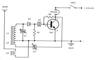
Mount tuning condenser C1 onto base. Push two 4BA bolts through base from countersunk side. Place two 4BA washers on each bolt. Line up holes in tuning condenser with bolts and screw bolts into condenser body, so that spindle points towards panel position.
Screw ply panel onto front of base, using two No.6 x 0.5" screws.
Mount on/off switch. Take two 6BA x 0.5" bolts, put a 6BA washer on each. Push bolts through from front of panel. Place a 4BA nut on each bolt. Slip on switch. Tighten a 6BA nut on each bolt.
Take the reaction trimmer C2 and put the brass 6BA bolt through the brass contact, screw on a 6BA nut and bend contact upwards as in diagram.
Mount the trimmer onto panel from the rear. Put on the 2BA washer and 2BA nut. Onto the long 6BA bolt through the centre, screw on a 6BA nut far enough to take the copper distance piece and another 6BA nut. Tighten the nuts against each other. Slip on black pointer knob and tighten grub screw.
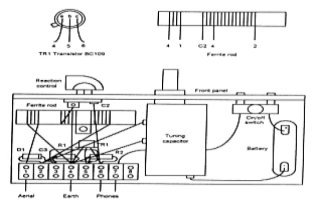
Take the 8 way or two 4 way terminal blocks. Unscrew all the contact screws to allow the entry of wires. Mount the block(s) onto the base using 2 or 4 copper plated nails. Knock these down between prominent moulding, using a suitable instrument. Refer to the terminals numbered 1 to 8, left to right. Terminal 8 is not used, but is a useful connection point if a further loudspeaker amplifier is added. Bending the component wires, make the following connections:
Connect short black wire from the tuning condenser to 4.
Connect white wire from tuning condenser to 2.
Connect long red wire from switch to 7.
Put C3, 220nF condenser, between 3 and 5.
Put D1 diode either way round between 2 and 3.
Put R2, 1M ohm resistor, between 5 and 6.
Put R1, 68k ohm resistor, between 3 and 4.
Put TR1 BC109's three leads e,b,c into 4,5 and 6. The key on the rim of the transistor must point downwards towards the base.
Connect green/orange wire from reaction trimmer to 6.
The Coil Take the ferrite rod and piece of gummed paper. Peel off backing and wrap on rod so that the longer side of paper is parallel with the rod. Take the coil of 32 s.w.g. enamelled copper wire, and carefully unwind avoiding kinks. Should this wire break, the ends must be soldered together. The enamel type insulation is also a flux. If the wire ends A,B,C,D and E are not soldered, the insulation must be scraped away, using the sandpaper, before taking to the terminal block and trimmer connections. Have short lengths of sellotape ready to anchor the beginning and end of windings on the rod. Wind all windings on the rod in the same direction. The end you start at will be the lower end.
Aerial coupling. Start about 5mm from the end of gummed paper. Leave some 6 or 7cm of wire. Hold in position on rod and anchor with tape. Wind on tightly and closely side by side 12 turns of wire, hold and anchor with tape. Leave 6 or 7cm of wire and cut off.
Reaction winding. Leave a gap of 1cm and start winding as for above, but wind on only 3 turns. Hold in position on rod between finger and thumb, make a 6 or 7cm loop of wire and twizzle round and round to bring the twists down to the rod. Do not cut wire, but continue with
Medium Wave winding. 60* turns wound tightly and closely side by side. Anchor with tape. Leave about 10cm of wire and cut off. [*To raise frequency, unwind a few turns] Clean all ends of wire connections, using sandpaper. Starting at the lower end of the rod, letter them A,B,C,D and E. Join A and D by twisting together.
To clip ferrite rod to base Take length of foam and push pin in between foam and backing. Lever off backing. Wrap foam around rod just above earth connection wires. Slip end of clip through slit and pull until loop is convenient size to put around rod. Make sure the clip is the right way round to screw it in position. Put rod through clip and pull plastic strap until a snug hold on rod. Snip off long end of strap so that the clip can be screwed onto base with the black japanned screw. Coil connections to terminal block A and D connect to 4. E connect to 2. B connect to 1. C connect to trimmer. Wrap end under bolt head several times and tighten.
Connect end of short red wire from switch to the positive(+) terminal of the battery by either wrapping it round, using a paper clip or small crocodile clip. Make sure the switch is in the off position.
Connect end of long black wire from tuning condenser to the negative(-) terminal of the battery and secure as above. Make sure of good electrical contacts with the battery.
External wire connections
(All to nearer terminals on block)
Phone Bare ends of white twin flex. Connect one pair of ends to the phone terminals, taking care not to allow loose whiskers of wire to short across. Connect the other pair of ends to 6 and 7.
Aerial Experiment with the length of wire from about 1 metre upwards. In the evening a shorter length gives clearer results. Bare one end and connect to 1.
Earth The set will not work well without an efficient earth. The length of wire is not critical but will need to reach from a suitable point to where the set is to be operated. Connection to a radiator water pipe may be adequate if the connection is sound, or drive a metal stake into the ground and lead a cable into the house. Do not attempt any kind of connection to the mains earth point. Connect your earth lead to 4.
Operating Suggestions
IMPORTANT: Check that the battery is connected the correct way, as it will damage the transistor if it is not. Before switching on, make sure the transistor and all other leads are correct, and that no wires are touching unless supposed to. Say a prayer and switch on! Adjust tuning and reaction to give the loudest and clearest signal. A shorter aerial increases selectivity but decreases sensitivity. Turning the tuning control anti-clockwise tunes to the lower frequencies (higher wavelength) of the band. Turning the reaction control anti-clockwise increases volume and selectivity, but if turned too far will cause oscillation (motor-boating) and distortion.
If receiver does not work
Turn off battery power.
Check the following in order:
The battery is in good condition.
The battery is connected the correct way round.
All the components are correctly connected and not shorting.
The phone wires are correct and not shorting.
The terminal block screws are tight.
The coil is the heart of the radio, so make it carefully. Cheek windings are correct and connection ends are properly cleaned.
The moving and fixed plates of the tuning condenser should not touch.
The receiver oscillates too much. You can reduce reaction by dismantling the reaction control. Remove one of the brass plates and carefully reassemble.
Philip Miller Tate
List of Components
The kit is intended to bridge the gap between the simple crystal set and more complicated radio receivers requiring soldering and a knowledge of electronics. It is the result of years of experimentation with circuits and construction techniques among Primary School children. The kit will be of interest to some children of or seven years upwards and with a little guidance, excellent results can be achieved. No soldering or knowledge of electronics is needed and full instructions and diagrams are supplied.
Technical The receiver covers the Medium Wave Band. It uses slow-motion tuning, a ferrite rod coil, one diode and one low noise transistor with reaction to increase volume and selectivity. The output is taken to a medium impedance balanced armature ear piece, which gives a pleasing sound.
Please check components against list
Quantity  Item	                 Quantity   Item
1    	  Wooden 'breadboard'	        1   Condenser 220nF
1	  Panel, plywood	        1   Resistor 1 Meg ohm
2	  No. 6 x ¾" screws             1   Resistor 68k ohm
1	  No. 5 x 3/8" screw	        1   Length of 32 s.w.g wire for coil
2	  4BA x ½" bolts.	        1   Ear piece
4	  4BA washers 1	                1   Ferrite rod
2	  4BA nuts               	1   Plastic strap + fixing screw
1	  2BA nut	                1   Length of foam
1	  2BA washer     	        1   Length white PVC twin flex
2	  6BA x ½" bolts	        1   Short copper distance piece
5	  6BA nuts	                1   Black pointer knob
2	  6BA washers	                1   Piece gummed paper
1	  6BA x ½" brass bolt           1   Piece sandpaper
4 or 2	  Copper plated nails	        1   Screwdriver
1	  8 way terminal block or	1   Diotran Radio Club badge
	  two 4 way blocks	        1   Set of detailed instructions
1	  2 gang tuning condenser	    and diagrams.
1	  Reaction Control (trimmer)
1	  Switch with leads
1	  Diode 0A91
1	  Transistor BC109