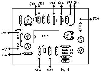

On any integrated circuit (including the UAA170 used in this project) pin 1 is always the pin immediately to the left of the notch at one end of the IC (and is so shown in the diagram on p.12).
When power is supplied to the circuit, the voltages on the UAA170 pins should be as follows:
Supply voltage Pin 10  11  13  14  15  16
13.8V stab.       13.8 2.5 5.6 5.6 0.4 1.8
9V (new PP9)       8.3 2.4 5.5 5.5 0.4 1.8
If you own a DVM with diode test function, place probes on anode and cathode of LEDs (as marked on the PCB layout) and they should light.
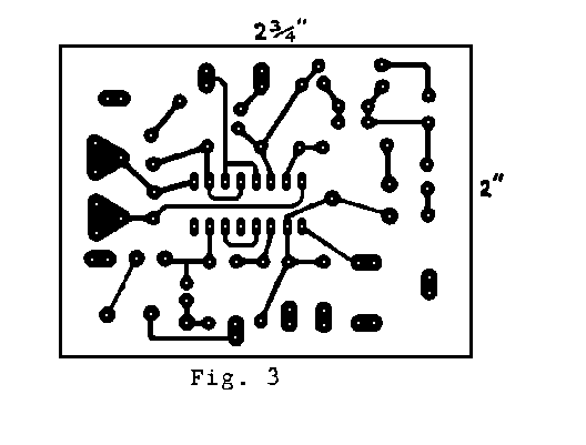
I must apologise for an omitted connection in the circuit diagram of the Function Generator (October Newsletter p.3). There should be a direct connection between N4 pin 6 and the junction of R6 and C4. This necessitates an amendment to the PCB layout (p.4 Fig.3). The corrected layout is given below.

