[ Eric Edwards writes in the How to get started in PIC Programming article: ... I spent many hours developing and experimenting with video mixers, faders and effects (FX) units ... ]
I like working with monochrome which is just as well because I cannot yet afford colour.
After the initial novelty had worn off, I began to think about special effects and I wondered if I could build a unit for this with my camera.
I once saw a camcorder demonstrated in a shop locally and I wondered if I could build a unit called a fader for myself.
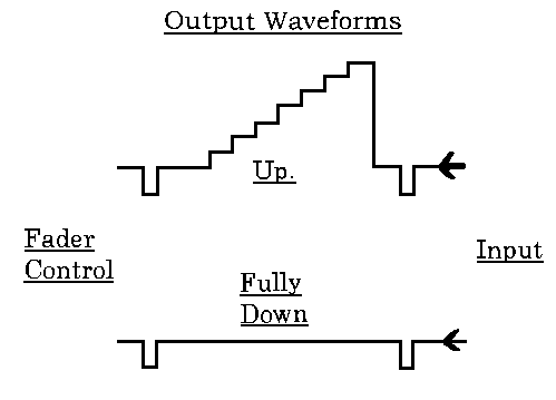
The unit allows you to fade a scene in at the beginning and fade it down to a blank screen at the end.
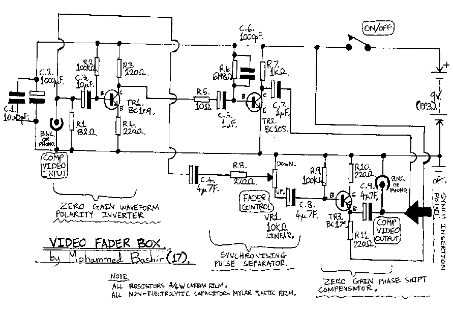
However this is no good for a composite video signal because the waveform contains synchroning pulses as well as video information and if you tried to use the simple potentiometer circuit you would find that the picture would break-up long before it became fully faded because the sync pulses would become too weak to hold the picture.
The answer is to have a route through the circuit which passes the synchronising information and is not affected by the setting of the fader control with another route which is affected by the control.
It works like this: suppose a new line of the picture is about to be traced out, first a line synch pulse is fed to C5 through R5. It is positive going and because of the high gain of the TR2 stage it saturates the transistor causing a strong clean negative going synch pulse to appear at the collector of TR2.
Now the negative going vision part starts but because the oversize coupling capacitor has been charged up during the line synch pulse and the input impedance of the TR2 stage is high, preventing the charge from leaking away too quickly, the charge on C5 gives a negative bias to TR2 causing it to cut off during the vision part of the line until the next synch pulse comes along and the action repeats.
So the waveform at the collector of TR2 consists only of synch pulses which are already of the right polarity to insert back into the output waveform.
The capacitor C6 is to curtail the frequency response of the TR2 stage at the frequency response of the TR2 stage as this improves the output quality: this transistor has a cut-off frequency of several hundred MHz although the highest frequency of interest in this stage is line synch at about 15kHz.
Going back to the Video fader then if a simple potentiometer arrangement were used in the all passing route through the circuit from input to output without the TR3 transistor stage, fading down a picture would also result in a horizontal panning effect as the phase shifted synch pulses took over from the non phase shifted synch pulses.
So then the phase shift compensator stage compensates for the phase shift in the synch only route by introducing some phase shift into the all passing route.
A more conventional method of construction can therefore be used than for earlier projects I have described in the Newsletter.
I used a Tripad board available from Maplin order code JP52G.
Wiring should be neat and as short as possible and it will all fit into a box about the size of old Betamax video cassettes.
I used clearly labelled sockets on opposite ends of the box for in-line operation. On/Off switch on another side and the fader control on top. I used slider pot. for the fader control on top. I used the slider pot. for the fader control but a rotary would work just as well.
Power Supply. I used a single PP3 battery which should give hours of use.
In Use: I tired the fader with several monitors. With the better monitors which have black level clamping in their video circuits it will fade to Black, If they do not have this circuitry it will fade to grey. I was able to make good quality VHS video tape recordings using this Fader Box.
Circuit Diagram of the Video Fader Box follows: